


WARN INDUSTRIES
PAGE 7
61584 Rev C0
NOTICE:
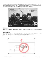
There are two wire terminals that must go to each of the contactor posts as shown, as there will
be two wires for motor-terminal “1” and two wires for motor-terminal “2”. One set going to the front of the
ATV (red connector) and the other set going to the rear of the bike (red connector).
FIGURE 9
6.
Refer to the WINCH OPERATOR’S MANUAL for full and complete details on wiring installation.
CAUTION:
The hook ( or toe-strap, etc.) should NEVER be hooked into either of the handles of the winch-carrier-
plate. This will cause permanent damage to the winch-carrier-plate.
TO MOTOR
TERMINAL NO. 2
(BLUE)
TO MOTOR
TERMINAL NO.1
(YELLOW)
TO NEGATIVE (-)
BATTERY TERMINAL
(BLACK)
TO POSITIVE (+)
BATTERY TERMINAL
(RED)
TERMINALS BACK TO
BACK ON CONTACTOR
POST


