background image

©2021 Warn Industries, Inc.WARN® and the WARN logo are trademarks of  Warn Industries Inc.

 2 

108376A0

N O T I C E

EQUIPMENT DAMAGE

• Always

 refer to the Installation and Specification Guide, supplied in the winch kit, for all wiring schematics and specific details on how to wire this WARN product to your vehicle.

• Always

 put the end of the actuator cable through the slot in the Termination Bracket. Terminating the cable through any other hole in the bracket will cause the bracket to not function properly and will drastically reduce the 

life of the actuator cable.

Read installation and operating instructions thoroughly.

MOVING PARTS ENTANGLEMENT HAZARD

Failure to observe these instructions could lead to minor or moderate injury

• Always

 take time to fully read and understand the installation and Operations Guide included with this product.

• Never

 operate this product if you are under 16 years of age.

• Never

 operate this product when under the influence of drugs, alcohol or medications.

Read installation and operating instructions thoroughly.

N O T E S

T A B L E   O F   C O N T E N T S

Tools Required ..................................................................................................................................................................................page 2

Parts List ..............................................................................................................................................................................................page 3

Torque Specifications .....................................................................................................................................................................page 3

Installation .....................................................................................................................................................................................page 4-7

Maintenance/Care ...........................................................................................................................................................................page 7


C A U T I O N

T O O L S   R E Q U I R E D

-  Standard wrenches

-   Standard sockets

-  Allen wrench

Содержание 108000

Страница 1: ...tallingthiskit Adrillingoperationwillcauseflyingmetalchips Flyingchipscancauseeyeinjury Alwaysuseextremecautionwhencuttingandtrimmingduringfitting Alwaysremovejewelryandweareyeprotection Neverleanoverbatterywhilemakingconnections Neverrouteelectricalcables o Acrossanysharpedges o Throughornearmovingparts o Nearpartsthatbecomehot Alwaysinsulateandprotectallexposedwiringandelectricalterminals Always...

Страница 2: ...able Read installation and operating instructions thoroughly MOVING PARTS ENTANGLEMENT HAZARD Failure to observe these instructions could lead to minor or moderate injury AlwaystaketimetofullyreadandunderstandtheinstallationandOperationsGuideincludedwiththisproduct Neveroperatethisproductifyouareunder16yearsofage Neveroperatethisproductwhenundertheinfluenceofdrugs alcoholormedications Read install...

Страница 3: ...ct unless otherwise specified in the instructions FASTENERSIZE FASTENERTORQUE lb ft N m 1 4 8 11 5 16 17 23 3 8 30 40 7 16 48 66 1 2 74 100 9 16 106 144 5 8 148 200 3 4 269 364 FASTENERSIZE FASTENERTORQUE lb ft N m M4 2 3 M5 4 5 6 M6 7 5 10 M8 18 25 M10 37 50 ITEM PN DESCRIPTION QTY B1 13454 M8 X 30MM FLANGE HEAD BOLT 4 B2 92600 M8 LOCK WASHER 4 B3 35136 PLOW PIN W SAFETY BAIL 2 B E F O R E Y O U ...

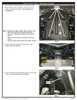
Страница 4: ... for reinstallation NOTE If vehicle is equipped with a winch remove now Disconnect the power leads from the battery Disconnect the yellow and blue cables from the winch Remove the four bolts securing the winch to the mount Slide the winch out through the side of the bumper 2 Remove the three lower hex heads screws Save hardware for reinstallation 3 Remove the upper hex head bolt from each side of ...

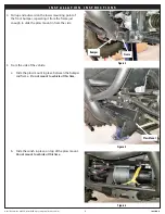
Страница 5: ...unting point of the front bumper separating it from the frame just enough to slide the plow mount in from the side 5 From the side of the vehicle a Slide the plow mount in place between the bumper and frame Do not mount to vehicle at this time b Slide the winch in place on top of the plow mount Do not mount to vehicle at this time Bumper Figure 4 Figure 5 Figure 6 Frame Plow Mount ...

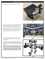
Страница 6: ...r and lower bumper mounting hardware see previous steps 2 and 3 TIP At this time it may be helpful to use a small Phillips screw driver to aid in aligning the components before installing the bolts 9 From under the bumper install four M8 bolts B1 and washers B2 to secure the plow mount fairlead bracket and winch to the vehicle Torque bolts to specifications on page 3 NOTE You will use the supplied...

Страница 7: ...is that may inhibit the part from moving freely See Warn Plow Operators Guide for more information 10 Reinstall the lower plastic skid plate and hardware to vehicle and bumper review previous step 1 11 Remove the rubber band from winch rope loop and attach the winch hook to the rope loop If you did not have a previously installed winch you may now complete the winch wiring portion of your winch in...

Отзывы: