background image

©2021 Warn Industries, Inc. WARN® and the WARN logo are trademarks of Warn Industries Inc.

 3 

101802A0

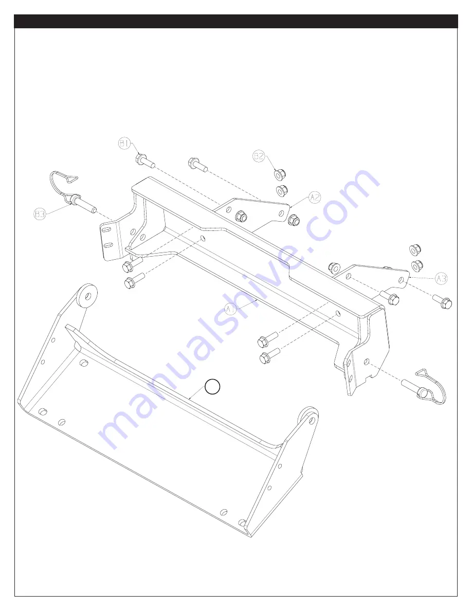
P A R T S   L I S T


ITEM  PART NUMBER 

DESCRIPTION 

QTY

  A1 

107646 

PLOW  MOUNT 

1

  A2 

107643 

SUPPORT BRACKET RH 

1

  A3 

107645 

SUPPORT BRACKET LH 

1

  A4 

106640 

PLOW FLANGE 

1

 ITEM 

PART NUMBER 

DESCRIPTION 

QTY

  B1 

65970 

M8 FLANGE HEAD BOLT 25MM 

8

  B2 

71588 

M8 FLANGE LOCK NUT 

8

  B3 

35136 

3/8 PIN W/ SAFETY BAIL 

2

A4

Содержание 107644

Страница 1: ...idesofmaterial priortodrilling andrelocateanyobjectsthatmaybedamaged Failuretoinspecttheareatobedrilledmayresultinvehicledamage electricalshock fireorpersonalinjury Alwayswearsafetyglasseswheninstallingthiskit Adrillingoperationwillcauseflyingmetalchips Flyingchipscancauseeyeinjury Alwaysuseextremecautionwhencuttingandtrimmingduringfitting Alwaysremovejewelryandweareyeprotection Neverleanoverbatte...

Страница 2: ...are page 5 T O O L S R E Q U I R E D Metric wrenches Metric sockets Wrench and socket extension N O T I C E EQUIPMENT DAMAGE Nevertowvehiclebyattachingatowbartotheeyeletsonthebumper Neverattachtowbarsdirectlytothebumper Damagetobumpermayoccur WARNbumpersarenotdesignedtobeusedforflattowing Consultwiththemanufacturerofyourtowbarsystemforthepropervehicletow barbrackets Read installation and operating...

Страница 3: ... P A R T S L I S T ITEM PART NUMBER DESCRIPTION QTY A1 107646 PLOW MOUNT 1 A2 107643 SUPPORT BRACKET RH 1 A3 107645 SUPPORT BRACKET LH 1 A4 106640 PLOW FLANGE 1 ITEM PART NUMBER DESCRIPTION QTY B1 65970 M8 FLANGE HEAD BOLT 25MM 8 B2 71588 M8 FLANGE LOCK NUT 8 B3 35136 3 8 PIN W SAFETY BAIL 2 A4 ...

Страница 4: ...kets to gussets using two M8 bolts B1 and locknuts B2 each side Do not completely tighten at this time to allow for adjustment 3 Align plow mount to the holes in the support brackets and attach using the four M8 bolts B1 and locknuts 4 Tighten ALL hardware at this time Start with the support brackets while pushing upward and in toward the vehicle as you tighten and lastly tighten the plow mount ha...

Страница 5: ...es 7 Complete your plow installation per your plow system installation instructions Figure 4 Figure 5 M A I N T E N A N C E C A R E 1 Inspect all parts on the plow plow mount and related hardware prior to each use Replace all hardware that appears rusted or de formed 2 Inspect all nuts and bolts on the plow plow mount and related hardware prior to each use Tighten all nuts that appear to be loose ...

Отзывы: