background image

11

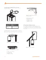
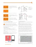
Figure 19 

Vertical flue set installation application

Implementation

L1


= 0.3 m.

L2


= 0.5 m. (45° bend equivalent length)

L3


= 1.0 m.

L4


= 0.5 m. (45° bend equivalent length)

L5


= 0.5 m.

L6


= 0.5 m.

L Total

 = 3.3 m. 

3.3 m. < Lmax = 5 m.

Correct in implementation

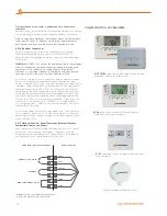
2.2.14. Hermetic Flue Type Use

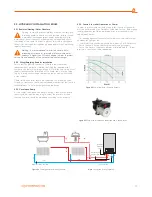
2.2.15. Installation at Partially Protected Exteriors

Installation Instructions: This combi can be installed in partially protected 

exteriors but not fitted in places at risk of atmospheric damage – and 

protected against poor weather.(rain, snow, etc.).

Frost protection:

 Combi device is equipped with a system that prevents 

frost by automatically activating the pump and boiler when the internal 

water is lower than 5°C.

Frost protection function only depends on below given conditions:

- If the combi is correctly connected to gas and electrical sources;

- If the combi is supplied from gas and electricity sources  in a fixed 

way;

- If the Combi is not in failure situation due to lack of ignition;

- If radiator installation pressure is full and radiator valves are open;

- Provided main components are not damaged, the combi is protected 

against frost up to -5°C environment temperature.

Lowest Temperature -5°C.

 In case the combi is installed in an 

environment with a temperature lower than -5°C, and gas supply is 

interrupted or passed into failure due to failing to make ignition, Frost 

Prevention System shall not be activated and frost/failure shall occur in 

the device. Following instructions should be followed for preventing the 

risk of frost:

- Heating circuit; anti freeze may be used with caution according to 

manufacturer's instructions.

In case of having flammable walls or passages in environments 

with Hermetic Flue Type, fire resistant insulation material is 

placed between the wall and exhaust gas relief pipe.

Materials used for manufacturing the combi are resistant against glycol 

and propylene based anti-frost liquids. Follow warnings by supplier 

companyinstructions for safe disposal..

- If the combi is correctly connected to the electrical source;

- If the main switch is on;

Under these conditions, the combi is protected against frost up to -5°C 

temperature.

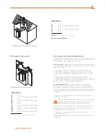
Implementation

L1


=0.2 m.

L2


=1.0 m. (90° bend equivalent length)

L3


=0.6 m.

L4


=1.0 m. (90° bend equivalent length)

L5


=0.8 m.

L6


=0.2 m.

L7


=1.0 m. (90° bend equivalent length)

L8


=0.5 m.

L9


=0.5 m. (45° bend equivalent length)

L10


=0.5 m.

L11


=1.0 m. (90° bend equivalent length)

L Total = 8.1 m. 

8.1 m. < Lmax = 18 m.

Figure 20 

Hermetic flue type installation

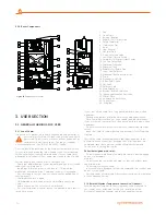
Содержание LAWA

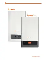
Страница 1: ...CONVENTIONAL COMBI BOILERS INSTALLATION USER MANUAL LAWA LAWAPLUS...

Страница 2: ...Lawa LawaPlus Enerwa E24 EnerwaPLUSE24...

Страница 3: ...Connections 2 2 17 Optional Controls Room Thermostat External Weather Temperature Sensor and Others 2 3 HYDRAULIC INSTALLATION RULES 2 3 1 Radiator Heating Water Structure 2 3 2 Filling Emptying Radi...

Страница 4: ...under any circumstances during installation use or maintenance operations and device warranty shall also be void Only the authorized Warmhaus Service is authorized to make the electrical connection of...

Страница 5: ...2 Installation Notes Figure 5 Exhaust gas flue set Do not use lighter matches Close valves of devices operating with natural gas and your gas meter Immediately evacuate the place with gas odour Natur...

Страница 6: ...for the combi boiler should be well secured The hanger plate given as standard with the combi should be installed according to the technique to a full or semi full brick wall according to installatio...

Страница 7: ...al operations Various alloy layers may be formed during transit of LPG gas in tanks depending on mixture compositions That causes a change in heating power of mixture assigned to the device and may co...

Страница 8: ...nd all wastes must be cleaned 2 2 10 Exhaust Gas Flue Pipe Set and Accessories Connection Flue accessory sets to be used in exhaust gas installation of Hermetic combis should be original Warmhaus flue...

Страница 9: ...nnection bolt installed on 90 flue bend of your combi to the flue output terminal and the clamp 3 should be insatlled on the EPDM connection bolt and slightly tighten with screw Figure 12 Then fit the...

Страница 10: ...Set Bend 45 b Flue Extension Pipe c Additional 90 Bend d Standard Flue Set Pipe Figure 16 II Two 90 bended sample flue installations d a b c a b c d 4 m Figure 14 Installation of reduction stamp Pipe...

Страница 11: ...ment temperature Lowest Temperature 5 C In case the combi is installed in an environment with a temperature lower than 5 C and gas supply is interrupted or passed into failure due to failing to make i...

Страница 12: ...poles and relying on the earth connection high voltage category 3rd class multiple poled disconnected should be envisaged on the same grid Your device is designed as enabling normal functioning betwee...

Страница 13: ...ef valves of the radiator Combi safety valve relief should be connected to a discharge cone Otherwise safety valve shall be activated and manufacturer shall not be responsible due to water discharge a...

Страница 14: ...ical fuse gas valve radiator and tap water valves Leave the Combi at Summer position and activate its Frost Protection function Shut off the combi during maintenance and repair operations to be perfor...

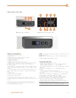
Страница 15: ...navy blue coloured backlight LCD screen 2 buttons Radiator 3 and Hot Tap Water 4 and 2 pcs RESET 2 and MODE 1 pushbuttons RESET It is used for re starting the combi and eliminating the failure in cas...

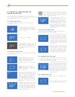
Страница 16: ...light turns off At that position you can adjust the temperature between 35 80 C with the Radiator CH temperature adjustment button 3 Temperature value increases when button is rotated clockwise or dec...

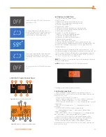
Страница 17: ...s lower than this value 18 Failure indicator The temperature value displayed on the combi screen has a 3 C tolerance depending on environmental conditions not arising from the combi Screen of PriwaPlu...

Страница 18: ...is the temperature value of water in the installation Hold the MODE button for switching on the combi when letter is available on the screen A cycle starts on the screen release the button when cycle...

Страница 19: ...diate responses to external weather temperature changes via smart and comfort operation Figure 32 Therefore it maintains an efficient and economic operation by reducing the radiator water temperaturew...

Страница 20: ...for LAWA PRIWA and ENERWA models Air discharge function can be activated by pressing the RESET button more than 5 seconds while CH button and DHW button are at maximum position Upon activation of thi...

Страница 21: ...uilding are open Call the authorized service in case of repeated after reset 1 E 42 Failure in pushbuttons Button failure Call the authorized service 1 E 43 Room thermostat OT communication failure Di...

Страница 22: ...time you must at least execute maintenance operations on a yearly basis in compliance with what is stated in the relative point at annual check and maintenance of the appliance in compliance with nat...

Страница 23: ...c Hot Water Heat Output kW 7 7 Max Domestic Hot Water flow rate t 30 C min 10 9 10 9 Min Domestic Hot Water flow rate min 1 5 1 5 Maximum water pressure bar 10 10 Minimum water pressure bar 1 5 1 5 Te...

Страница 24: ...0 25 37 I2H I2E I2E I2L I2ELL I 2H I3P NUMBER OF CHOOSED CONNECTING CONDITIONS Used gas G20 G20 G25 G25 G20 G25 G20 G31 Countries of destination AT BG CH CZ DK EE ES FI GB GR IE IT LT LV NO PT RO SE S...

Страница 25: ...25...

Страница 26: ...26...

Страница 27: ...27...

Страница 28: ...CONVENTIONAL COMBI BOILERS INSTALLATION USER MANUAL LAWA LAWAPLUS Instruction booklet code of Lawa LawaPlus 150 11 606 000004 Revision Date 12 2016...

Отзывы: