Warmboard Warmsource-N Скачать руководство пользователя страница 4

WARMBOARD COMFORT SYSTEM  //  GAS

4

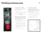
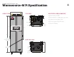
INCLUDED, PRE-PLUMBED

The following components are pre-plumbed inside 
the Warmsource-N/P unit:


f

Automatic air vent


f

Expansion tank (preset at 15 PSI, can be reset with  
a bike pump and ball valve in the closed position)


f

Constant pressure circulation pump(s), pre-set  
to “Constant Pressure    ” by Warmboard Inc.

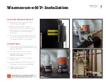
INCLUDED, NOT PRE-PLUMBED

The following are included with Warmsource-N/P 
but NOT pre-plumbed. Refer to the WCS Design 
Drawings for location and pipe sizing:


f

Pressure reducing valve (maintains a constant  
water pressure of 12-18 PSI, and adds “make up” 
water for evaporation)


f

Backflow preventer (required by code in many 
jurisdictions, it prevents water in the closed-loop 
system from mixing with the domestic water)


f

Air purging valves (a 1 

1/4

" combo ball valve/hose 

bib, along with several smaller valves, for easy air 
purging [be sure to install in the correct location and 
water flow direction])


f

Temperature and pressure (T&P) relief valve
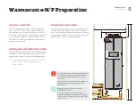
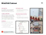
WCS DESIGN DRAWINGS

Our WCS Design Drawings list all the necessary 
plumbing and mechanical materials. Reference this 
document regularly. Before proceeding, all boiler 
components must pre-plumbed per the 

HTP UFT 

Install Manual

, including:


f

PVC intake and exhaust venting (

pages 31-39


f

Gas (

pages 46-47

) and condensation line (

page 40

)


f

T&P relief valve discharge (

page 30


f

1/2" cold water line from the domestic water  
supply to the pressure reducing valve  
(WCS Design Drawings)

Plumbing and Mechanical

Содержание Warmsource-N

Страница 1: ...1 1 800 556 0595 for assistance FOR USE WITH Warmsource N natural gas boiler Warmsource P propane gas boiler Warmboard Comfort System INSTALLATION GUIDE 1021...

Страница 2: ...e exhaust gas vent is required 7 The constant pressure circulation pump s inside Warmsource N P adjust flow rates depending on the needs of each zone 8 Once system plumbing is complete test the system...

Страница 3: ...and WCS f Foundation and joist f Install Warmboard S f Install tubing some loops before walls f Frame walls roof sheeting f Install tubing manifolds some loops f Install all 120 volt electrical boxes...

Страница 4: ...red by code in many jurisdictions it prevents water in the closed loop system from mixing with the domestic water f Air purging valves a 1 1 4 combo ball valve hose bib along with several smaller valv...

Страница 5: ...ibution lines for 15 minutes at 100 PSI International Mechanical Code section 1208 1 MINIMUM CLEARANCES This illustration shows the recommended minimum dimensions for the Warmsource N P mechanical are...

Страница 6: ...301 2 56 11 4 Brass Union supply 11 4 Brass Union return 3 Air Intake T P Relief Valve 3 Exhaust 53 4 57 8 6 3 4 Gas line left side preferred right side OK Condensation Discharge Line 361 2 171 2 21 2...

Страница 7: ...cket the unit weighs 150lbs and requires two individuals to move safely CONNECTIONS f Connect the PVC intake and exhaust lines gas line condensation discharge line and T P relief discharge line per th...

Страница 8: ...ng the system with water for 10 15 minutes until air cannot be seen or heard escaping the hose f Close the fast fill lever then slowly close hose bib A f Ensure the pressure gauge located inside Warms...

Страница 9: ...p 3 Plug Warmsource N P into the 120 volt outlet and confirm the system is ON using the rocker switch and power button circled in the photo to the right Warmsource N P will reach the target temperatur...

Страница 10: ...sign Drawings CONTROLS Warmboard Controls consist of the following f 120 volt thermostats one per heating zone f 120 volt Manifold Controller one per manifold f 24 volt solenoid valve loop actuators o...

Страница 11: ...inaccurately If there are any discrepancies regarding the thermostat or zoning contact us immediately f Remove the appropriate thermostat from the box f Grip the face of the thermostat on the sides w...

Страница 12: ...rminal connection AC1 Fan on the Smart Reset Controller SRC f Connect the wires from the AC unit to the terminal block accordingly RC 24v power red wire Y Cooling Call yellow wire G Fan green wire f T...

Страница 13: ...inutes the green lights will turn blue indicating that the actuators have opened and water is flowing to the zone f If something does not appear to be working properly consult your Warmboard Engineere...

Страница 14: ...E ARE EXPRESSLY EXCLUDED FAILURE TO INSTALL WARMBOARD PRODUCTS ACCORDING TO MANUFACTURER S INSTRUCTIONS WILL VOID ALL APPLICABLE WARRANTIES IT IS EXPRESSLY UNDERSTOOD THAT WARMBOARD IS NOT RESPONSIBLE...

Отзывы: