


7
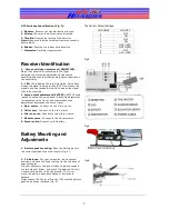
DIP Switches Identification (Fig. 3):
1.
Elevator.
Reverse the elevator servo direction.
2. Aileron.
Reverse the aileron servo direction.
3. Throttle.
Reverse the throttle stick direction.
Note:
Make sure that the throttle stick works correctly
before flight,
4. Rudder.
Reverse the rudder stick direction.
7.
Simulator.
Simulator signal switch.
Receiver Identification
1. Gyro sensitivity adjustment (SENSITIVE).
Adjust the sensitivity according to the flight
performance. Clockwise adjustment increases the
sensitivity and counterclockwise adjustment decreases
the sensitivity.
2. LED.
LED indicates the receiving status. Quick flash
means the signal is being received; LED on means the
signal has been received; slow flash means the signal
fails to be received.
3. Servo extent adjustment (EXTENT).
EXTENT knob
is used to set up the servo travel. Clockwise adjustment
increases the servo travel, and counterclockwise
adjustment decreases the servo travel.
4.
Main motor.
Connect to the main motor.
5.
Tail motor.
Connect to the tail motor.
6.
Aileron servo.
Connect to the aileron servo.
7.
Elevator servo.
Connect to the elevator servo.
8. Power cable.
Connect to the battery.
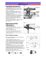
Battery Mounting and
Adjustments
1. Battery pack mounting.
Place the battery pack in
the correct position of your helicopter (Fig. 5).
2. CG balance.
Put your helicopter in a horizontal
position and have the flybar vertical to the tail truss of
your helicopter.
Lift your helicopter using your index fingers to support
the two sides of flybar, and check the balance. The tail
truss should be level with the ground. If it is not,
move the battery pack backwards or forwards to
balance.
Always check the Center of Gravity (CG) with the battery
pack and canopy installed (Fig. 6).
The Factory Default Settings:
CHANNEL
ON/OFF
1
OFF
2
ON
3
OFF
4
ON
5
NOT USED
6
NOT USED
7
OFF
8
NOT USED
Fig.4
Fig.5
Fig.6


