15
Voltage Input Type Outputs (Non-Contact Closure)
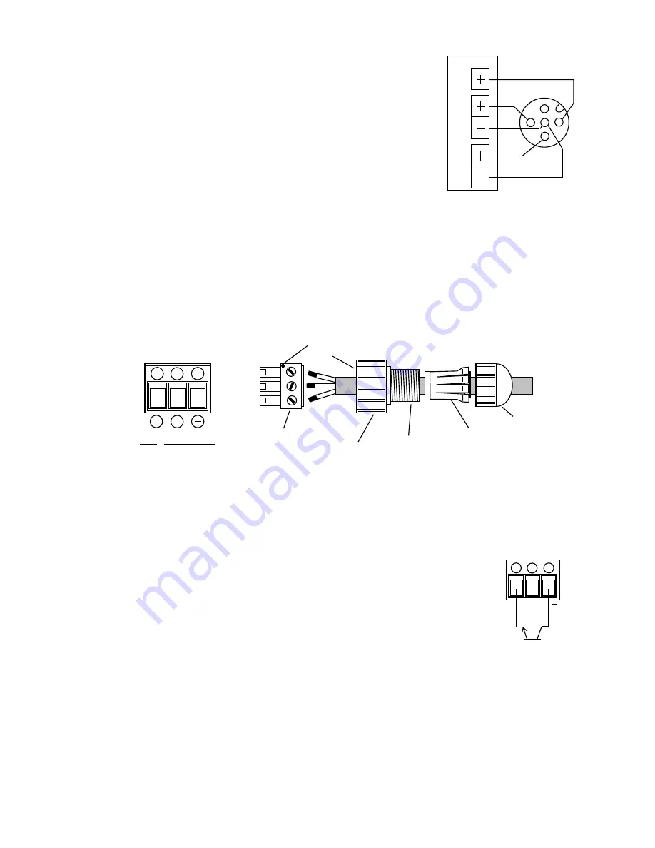
PIN 1 will take a voltage in from an external source (max
24VDC). When this external voltage is present, then both
relays will independently switch the input voltage. Both
outputs can be used simultaneously. The figure to the left
shows a schematic with the output relays configured to
switch the powered input. This setup can only be used with
voltage input type circuits (not contact closure types) such as
those commonly found in a PLC.
B.
EK Pumps and the ‘R’ control module
One custom watertight connector is used for the digital input and stop/start connections on the
EK pumps. There are no outputs on the EK pumps. The Connector Holder is keyed to fit into
the pump only one direction. There is a set of painted alignment marks on the connector and
connector holder that identify the correct orientation of the connector. Be sure to double check
that the connector is installed properly into the connector assembly before installation onto the
pump.
Digital Control
The external pulse input should not exceed 360 pulses per minute (6Hz)
and the pump will output one stroke for every input pulse. The control
signal can be a contact closure type switch (reed) with a max load of 1mA
or a solid state device. If a solid state device is used, the external circuit
should be capable of switching 5VDC at 1.2mA with an active duty cycle
pulse width of 5ms to 100ms (actual closure time).
To connect the pulse input from an external device, wire Terminal 4 and
Terminal 6 from the contact closure. If using a solid state switching
device, wire the connector ensuring that Terminal 4 is positive (+) and
Terminal 6 is Common (-).
Connector
Lock Nut
Connector
Holder
Gasket &
Adapter
Cord Nut
4
5
6
+
+
Connector
PIN FUNCTION
4 External Digital Input
5 Stop/Start Input
6 Common
Orientation
Marks
+
4
5
6
Connector
Digital
Input
Stop/
Start
Input
Voltage type
Input
1
5
3
4
2
Sync
Pulse
Input
Power
OUT
PLC
EW
Connector 1


