


EPSITRON®
Function Description
31
787-1675 Switched-Mode Power Supply with Integrated UPS Charger and Controller
Manual
Version 1.0.0
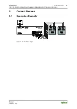
6.4.1.2 Connecting a Battery Module from a Third-Party Manufacturer
Before connecting, check whether the battery module you wish to use is a
rechargeable
•
lead cell battery,
•
lead-gel battery or
•
lead-acid absorbed glass mat (AGM) battery
with a nominal voltage of 24 VDC. The unit may only be operated with these
types of batteries!
1.
Ensure that the unit is not live by removing the power supply and any fuse
which may be present in the battery module.
2.
Connect the "Battery" (B+/B-) terminal of the unit to the "Battery" (+/-)
terminal of the battery Ensure that the polarity is correct!
3.
Re-install the fuse in its receptacle on the battery module.
4.
Connect the power supply.
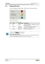
The green LED on the unit will then light up; the yellow LED may also light up.
The red LED lights up when applying the power supply!
A fault is present is the red LED remains lit after power has been applied. If this
happens, refer to the table "Signaling via LEDs" given in this manual!
Pos: 57 /Serie 787 (EPSITRON)/F unkti onsbeschrei bung/Batteriepr üfungen 787- 1675 @ 13\mod_1343027870471_21.doc @ 100680 @ 23333 @ 1
6.5
Battery Testing
Different battery tests are carried out, depending on the operating status of the
batteries. Corresponding alarms or messages are generated if the unit detects any
abnormal conditions.
6.5.1
Charging
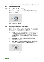
Batteries are charged during normal operation. The charge level is checked for
this every 60 seconds. If the charge level for the batteries is less than 85 % the
yellow LED lights up and the signal output "Bat. Charge" is activated.
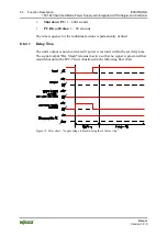
6.5.2
Presence Test
The unit performs a presence test automatically every 60 seconds. This test checks
whether the battery module is properly connected and operational. A brief and
slight load is applied to the batteries during this test. This test is only performed
when the unit is in normal operation.