


22
Device Description
EPSITRON®
787-1675 Switched-Mode Power Supply with Integrated UPS Charger and Controller
Manual
Version 1.0.0
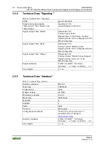
3.5.4
Technical Data "Signaling"
Table 14: Technical data - "Signaling"
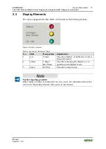
LEDs
green/red/yellow
Supply for signal outputs
"Bat. Alarm", "Bat. Mode" and
"Bat. Charge"
maximum 30 V,
current limited to 200 mA
Signal output "Bat. Alarm"
Maximum 30 V.
Contact open: Fault/
Replacement of the battery module;
Signal options can be configured via the
RS-232 interface
Signal output "Bat. Mode"
Maximum 30 V.
Contact closed: Battery mode;
Signal options can be configured via the
RS-232 interface
Signal output "Bat. Charge"
Maximum 30 V.
Contact closed: Battery being charged;
Signal options can be set via the
RS-232 interface
Signal terminals
CAGE CLAMP
®
, 721 Series;
0.08 mm
2
… 2.5 mm
2
; AWG 28 … 12
Line length
≤ 3 m
3.5.5
Technical Data "Interface"
Table 15: Technical Data: Interface
Interface standard
RS-232
Data lines
TxD/RxD
Control lines
none
Output voltage
24 VDC
Reference potential
0 VAC
Baud rate
9600 baud
Data bits
8
Stopbits
1
Parity
none
Protocol
On request
Configuration Software
759-870 V2, from Version 2.5
(available free of charge at
Interface modules
CAGE CLAMP
®
, 734 Series;
0.08 mm
2
… 0.5 mm
2
; AWG 28 … 20
Line length
≤ 3 m