


30
Function Description
EPSITRON®
787-1675 Switched-Mode Power Supply with Integrated UPS Charger and Controller
Manual
Version 1.0.0
Pos: 56 /Serie 787 (EPSITRON)/F unkti onsbeschrei bung/Batteriemodul e 787-1675 @ 13\mod_1342686258943_21.doc @ 100573 @ 2344 @ 1
6.4
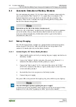
Automatic Detection of Battery Modules
The unit automatically detects 787-87x Series battery modules connected to the
system, provided the "Bat. Control" (C+/C-) signal lines are connected. The
internal temperature sensor can also be evaluated with these modules. The
charging voltage can be re-adjusted as required during the float charge phase
based on the measured temperature.
Extend the service life of the battery modules used!
The service life of the battery modules used is reduced if the ambient conditions
are not favorable. Always ensure therefore that the batteries are not used in
excessive ambient temperatures. Information on this is given in the battery
manufacturer's data sheet.
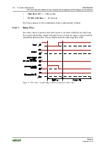
6.4.1
Battery Charging
The 787-87x Series battery modules are equipped with an internal temperature
sensor of type NTC K164 (4.7 k
Ω),
which measures the temperature of the
module. It is installed directly in each battery module.
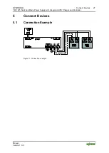
6.4.1.1 Connecting the 787 Series Battery Modules
1.
Ensure that the unit is not live by removing the power supply and the fuse in
the battery module.
2.
Connect the "Battery" (B+/B-) terminal of the unit to the "Battery" (+/-)
terminal of the battery Ensure that the polarity is correct!
3.
Connect the "Bat. Control" (C+/C-) terminal of the unit to the "CTRL"
(Ctrl+/Ctrl-) terminal of the battery. Again, ensure proper connection of the
correct terminals (polarity)!
4.
Re-install the fuse in its receptacle on the battery module.
5.
Connect the power supply.
The green LED on the unit will then light up; the yellow LED may also light up.
The red LED lights up when applying the power supply!
A fault is present is the red LED remains lit after power has been applied. If this
happens, refer to the table "Signaling via LEDs" given in this manual!