background image

WAGO-I/O-SYSTEM 750 

Notes about this Documentation 

750-658 CAN Gateway 


Manual 


Version 1.2.1, valid from FW/HW-Version 01/01 


1.4 

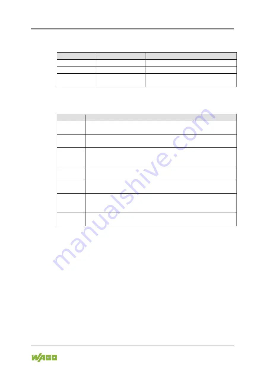
Number Notation 


Table 1: Number Notation 

Number Code 

Example 

Note 

Decimal 

100 

Normal notation 

Hexadecimal 

0x64 

C notation 

Binary 

'100' 

'0110.0100' 

In quotation marks, nibble separated 

with dots (.) 


1.5 

Font Conventions 


Table 2: Font Conventions 

Font Type  Indicates 

italic


Names of paths and data files are marked in italic-type.  

e.g.: 

C:\Program Files\WAGO Software


Menu


Menu items are marked in bold letters.  

e.g.: 

Save


A greater-than sign between two names means the selection of a 

menu item from a menu.  

e.g.: 

File

 >

 New


Input 

Designation of input or optional fields are marked in bold letters,  

e.g.: 

Start of measurement range


“Value” 

Input or selective values are marked in inverted commas.  

e.g.: Enter the value “4 mA” under 

Start of measurement range

[Button] 

Pushbuttons in dialog boxes are marked with bold letters in square 

brackets.  

e.g.: 

[Input]


[Key] 

Keys are marked with bold letters in square brackets.  

e.g.: 

[F5]


Содержание 750-658

Страница 1: ...Manual WAGO I O SYSTEM 750 750 658 CAN Gateway Version 1 2 1 valid from FW HW Version 01 01...

Страница 2: ...87 84 45 55 E Mail support wago com Every conceivable measure has been taken to ensure the accuracy and completeness of this documentation However as errors can never be fully excluded we always appr...

Страница 3: ...logy 15 4 Device Description 16 4 1 View 18 4 2 Connectors 19 4 2 1 Data Contacts Local Bus 19 4 2 2 Power Jumper Contacts Field Supply 20 4 2 3 CAGE CLAMP Connectors 22 4 3 Display Elements 23 4 4 Sc...

Страница 4: ...8 Connect Devices 44 8 1 Connecting a Conductor to the CAGE CLAMP 44 8 2 Connect CAN Bus 45 9 Configuration and Parameterization 46 9 1 Configuration and Parameterization with WAGO I O CHECK 47 9 1 1...

Страница 5: ...2 1 The Handshake Byte 86 12 1 3 Communication Phases 87 12 1 3 1 Synchronization 87 12 1 3 1 1 Mailbox Commands 87 12 1 3 1 2 Acknowledgement 88 12 1 3 1 3 Signaling 88 12 1 3 1 4 Finite Automation 8...

Страница 6: ...rding to the instructions in this manual and in the manual for the used fieldbus coupler or controller Consider power layout of the WAGO I O SYSTEM 750 In addition to these operating instructions you...

Страница 7: ...Indicates a moderate risk potentially hazardous situation which if not avoided could result in death or serious injury Personal Injury Indicates a low risk potentially hazardous situation which if no...

Страница 8: ...ntation WAGO I O SYSTEM 750 750 658 CAN Gateway Manual Version 1 2 1 valid from FW HW Version 01 01 Additional Information Refers to additional information which is not an integral part of this docume...

Страница 9: ...and data files are marked in italic type e g C Program Files WAGO Software Menu Menu items are marked in bold letters e g Save A greater than sign between two names means the selection of a menu item...

Страница 10: ...nvironments All changes to the coupler or controller should always be carried out by qualified personnel with sufficient skills in PLC programming 2 1 3 Use of the 750 Series in Compliance with Underl...

Страница 11: ...requirements These modules contain no parts that can be serviced or repaired by the user The following actions will result in the exclusion of liability on the part of WAGO Kontakttechnik GmbH Co KG R...

Страница 12: ...onic equipment sent to your local collection point Improper disposal of electrical and electronic equipment can be harmful to the environment and human health 2 1 4 1 2 Packaging Packaging contains ma...

Страница 13: ...access to such equipment and fixtures to authorized qualified staff only by means of specific keys or tools Ensure disconnect and overcurrent protection The device is intended for installation in aut...

Страница 14: ...bove mentioned materials Clean tools and materials are imperative for handling devices modules Clean only with permitted materials Clean housing and soiled contacts with propanol Do not use any contac...

Страница 15: ...are not addressed but the messages are identified The devices are allowed to send messages whenever the bus is available Bus conflicts are solved by assigning messages a specific priority This priori...

Страница 16: ...n blocks The 750 658 module can be used with the fieldbus couplers and controllers of the WAGO I O SYSTEM 750 of the specified version or higher listed in the Compatibility list table Table 3 750 658...

Страница 17: ...ller 750 849 05 750 889 07 BACnet Fieldbus controller 750 830 03 LONWORKS Fieldbus coupler 750 319 05 Fieldbus controller 750 819 09 Various PFC200 750 820x 02 Table 4 750 658 Compatibility List IPC B...

Страница 18: ...nd for Figure View Pos Description Details See Section 1 Marking possibility with Mini WSB 2 Status LEDs Device Description Display Elements 3 Data contacts Device Description Connectors 4 CAGE CLAMP...

Страница 19: ...tacts which are available as self cleaning gold spring contacts Figure 2 Data Contacts Do not place the I O modules on the gold spring contacts Do not place the I O modules on the gold spring contacts...

Страница 20: ...ure 3 Power Jumper Contacts Table 6 Legend for Figure Power Jumper Contacts Contact Type Function 1 Spring contact Potential transmission Uv for field supply 2 Spring contact Potential transmission 0...

Страница 21: ...ual Version 1 2 1 valid from FW HW Version 01 01 Use supply modules for ground earth The I O module has no power jumper contacts for receiving and transmitting the earth potential Use a supply module...

Страница 22: ...CAN ground 0 V 3 Supply voltage 0 V Shield 4 Shield connection DIN rail CAN L 5 CAN low 24 V 6 Supply voltage 24 V Shield screen 8 Shield connection DIN rail Use shielded signal lines Only use shield...

Страница 23: ...CAN bus properly initialized CAN Rx B Red CAN telegram could not be received Green CAN telegram received C Not assigned D Not assigned Local bus RUN E Green Data exchange via mailbox or register comm...

Страница 24: ...24 Device Description WAGO I O SYSTEM 750 750 658 CAN Gateway Manual Version 1 2 1 valid from FW HW Version 01 01 4 4 Schematic Diagram Figure 6 Schematic Diagram...

Страница 25: ...IP20 Data width internal 8 bytes 12 bytes 16 bytes 20 bytes 24 bytes 32 bytes 40 bytes 48 bytes 4 5 2 Supply Table 10 Technical Data Supply Power supply Via system voltage local bus 5 V DC and power j...

Страница 26: ...000 kbit s Auto baud rate Diagnostic information Local bus status via status byte event codes via the mailbox 4 5 4 Connection Type Table 12 Technical Data Field Wiring Wire connection CAGE CLAMP Cros...

Страница 27: ...altitude without temperature derating 0 2000 m with temperature derating 2000 5000 m 0 5 K 100 m max 5000 m Relative humidity Max 5 95 without condensation Pollution degree 2 Protection type IP20 Resi...

Страница 28: ...ty Marking UL508 Korea Certification MSIP REM W43 MSM750 The following Ex approvals have been granted to 750 658 I O modules T V 14 ATEX 148929 X II 3 G Ex nA IIC T4 Gc IECEx TUN 14 0035 X Ex nA IIC T...

Страница 29: ...01 01 4 7 Standards and Guidelines 750 658 I O modules meet the following requirements on emission and immunity of interference EMC CE Immunity to interference EN 61000 6 2 EMC CE Immunity to interfe...

Страница 30: ...elegrams can be transferred to the controller CAN telegrams can be sent to other CAN nodes Specific CAN bus diagnostics can be displayed The data can be transferred by the Mailbox 2 0 protocol among o...

Страница 31: ...e in the bus network That means that the transmitter is activated from the hardware side In this operating mode telegrams can be received and sent If CAN telegrams are received confirmation is sent to...

Страница 32: ...configured CAN telegram is sent also depends on the trigger configuration The following settings are possible Send on request Send on change Cycle time Figure 9 Map CAN Telegrams in Output Direction 5...

Страница 33: ...he so called toggle byte in the process image Send groups can be assigned to telegrams to be sent If one or more bits are inverted in the toggle byte the respective send groups are affected All assign...

Страница 34: ...telegrams of a defined range can also be received and sent via the mailbox The data format is identical to the data formats of the Sniffer and Transparent operating modes Note modified access times C...

Страница 35: ...e than receiving these telegrams on the CAN bus Thus several CAN telegram of the same CAN ID may be cached in the I O module The following settings can be made 1 Overwrite 2 Keep All 5 2 1 Overwrite S...

Страница 36: ...it 3 Bit 2 Bit 1 Bit 0 0 res res res res res res res 1 0 Read register 1 Write register Register number Reserved Status byte Table 18 Status Byte Status Byte Bit 7 Bit 6 Bit 5 Bit 4 Bit 3 Bit 2 Bit 1...

Страница 37: ...smission method is the basis If the Mailbox is active control byte bit 7 0 it is used to transfer configuration parameterization and diagnostic data Bytes 1 to 6 of the local process image are used by...

Страница 38: ...8 If the 2 0B Extended Frame setting is activated CAN telegrams have the following structure Table 20 Structure of CAN Telegrams with the 2 0B Extended Frame Setting Byte Name Bits 0 Identifier byte...

Страница 39: ...in Transparent Operating Mode The CAN user data range on the process image is symmetrical for both data directions Figure 11 Process Image in the Transparent Operating Mode 6 2 1 Mailbox See section...

Страница 40: ...perating mode see respective section It is one byte and is used to send CAN telegrams on request If one or more bits are inverted the respective send groups are affected All assigned telegrams are cre...

Страница 41: ...with power contacts blade contacts cannot be linked to I O modules with fewer power contacts Risk of injury due to sharp edged blade contacts The blade contacts are sharp edged Handle the I O module c...

Страница 42: ...tion the I O module so that the tongue and groove joints to the fieldbus coupler or controller or to the previous or possibly subsequent I O module are engaged Figure 13 Insert I O Module Example 2 Pr...

Страница 43: ...alid from FW HW Version 01 01 7 2 2 Removing the I O Module 1 Remove the I O module from the assembly by pulling the release tab Figure 15 Removing the I O Module Example Electrical connections for da...

Страница 44: ...to each CAGE CLAMP Do not connect more than one conductor at one single connection If more than one conductor must be routed to one connection these must be connected in an up circuit wiring assembly...

Страница 45: ...vices 45 750 658 CAN Gateway Manual Version 1 2 1 valid from FW HW Version 01 01 8 2 Connect CAN Bus Connect a terminating resistor of 120 parallel to the CAN H and CAN L lines if the I O module is th...

Страница 46: ...N lib of the WAGO I O PRO library Configuration software using device description files e g PROFIBUS GSD see appendix section Configuration Using PROFIBUS GSD Configuration and parameterization via WA...

Страница 47: ...ameterization of the operating modes of the I O module Diagnostics of the I O module WAGO I O CHECK You can obtain the WAGO I O CHECK software on a CD under Item No 759 302 This CD contains all the ap...

Страница 48: ...areas Figure 18 Configuration Dialog of the I O Module 1 Toolbar 2 Function area 3 Diagnosis area These areas will be explained in more detail in the following sections 9 1 1 1 Toolbar The toolbar in...

Страница 49: ...for the Transparent operating mode and puts the I O module in this operating mode Mapped Mode Opens the function area for the Mapped operating mode and puts the I O module in this operating mode Read...

Страница 50: ...Table 22 Buttons on the Main Menu Button Function Description PII Opens the specific PII function area in the Mapped operating mode PIO Opens the specific PIO function area in the Mapped operating mo...

Страница 51: ...rameters see section Configuration Dialog Factory Settings Resets the I O module to the factory settings Help Opens the WAGO I O CHECK online help Info Opens the information dialog Exit Closes the con...

Страница 52: ...opening files 2 Select a parameter file 3 In the Select data dialog select the parameters to be loaded from the file Only parameters in the selected file can be selected More information on the liste...

Страница 53: ...perating mode CAN parameter Filter If the checkbox is selected the selected parameters are loaded in the application Mapping rule input Mapping rule output Write all selected data after loading into t...

Страница 54: ...ostics Figure 22 Turn on Advanced Mailbox Diagnostics If there is an error an error code appears in the diagnostics area and an LED lights up on the I O module There is different signaling depending o...

Страница 55: ...e in bytes Enter the corresponding value in the Length input field Figure 23 Set Mailbox Length Set the mailbox size in the Sniffer and Transparent operating modes Set the mailbox in these operating m...

Страница 56: ...way Manual Version 1 2 1 valid from FW HW Version 01 01 9 1 3 3 Setting the Process Image Size Set the process image size The following settings are possible 8 bytes 12 bytes 16 bytes 20 bytes 24 byte...

Страница 57: ...ersion 1 2 1 valid from FW HW Version 01 01 9 1 4 Function Area in the Sniffer Mode All CAN telegrams received are listed in the Receive dialog Figure 25 Function Area in the Sniffer Mode The followin...

Страница 58: ...owing interaction options are available Send button Sends the CAN telegram CAN ID input field The CAN ID of the CAN telegram to be sent can be entered here in hexadecimal format If the input field is...

Страница 59: ...user data length of the CAN telegram to send can be specified here value range 0 8 Data input field The user data of the CAN telegram to be sent can be entered here in hexadecimal format If the input...

Страница 60: ...ss image oriented display left The CAN display right These show the current mapping rules for the process image of the input Figure 27 Function Area in the Mapped Mode PII View The following interacti...

Страница 61: ...the dialog Figure 28 Add mapping rule Dialog Change button Opens the Change mapping rule dialog to go to the configuration dialog All values except the CAN ID can be edited The interaction options are...

Страница 62: ...available Add button Opens the Add mapping rule dialog to go to the configuration dialog The following interaction options are available in the dialog itself CAN ID input field The CAN ID of the CAN t...

Страница 63: ...are sent with activated Remote Transmit Request Bit If the checkbox is not selected data telegrams are sent Send on change checkbox If the checkbox is selected a CAN telegram can be generated and sen...

Страница 64: ...alog to go to the configuration dialog All values except the CAN ID can be edited The interaction options are identical to those in the Add mapping rule dialog Figure 32 Change mapping rule Dialog Del...

Страница 65: ...n the Data Format selection box to select a data format You can select the following formats 2 0A Standard 11 bit 2 0B Extended 29 bit If the 2 0A Standard 11 bit format is selected only CAN telegrams...

Страница 66: ...baud rate The following settings are possible 10 kBit s 20 kBit s 50 kBit s 125 kBit s 250 kBit s 500 kBit s 800 kBit s 1000 kBit s and Auto Baudrate Figure 34 Set CAN Baud Rate If the Auto Baud Rate...

Страница 67: ...ect one or more of 6 pass through filters Activate the respective Activated checkbox after the filter 2 Specify the upper and lower limits for the selected filter Enter the respective values in the Lo...

Страница 68: ...ted The protocol data may be unusable because all data of a CAN ID is required in general Select the Keep All setting here CAN telegrams of a defined range can also be received and sent via the mailbo...

Страница 69: ...n be downloaded at www wago com There are the following deviations General The Load and Save functions are automated in the application Some files cannot be manually loaded or saved Therefore the Open...

Страница 70: ...AN_Gateway lib provides the option to start up the I O module using the corresponding function blocks Library cannot be used to set the process image size The WAGO I O PRO library WagoLib_CAN_Gateway...

Страница 71: ...e error 3EF 1007 Red CAN HW in BUS OFF State Error I O module in BUS OFF State 3F0 1008 Red CAN Rx Error Counter 127 The internal counter receive direction is greater than 127 The I O module is initia...

Страница 72: ...6 Red ExtRegCom Data Length Err Advanced register communication Length of the telegram is wrong 7D7 2007 Red ExtRegCom Unknown Table Err Advanced register communication unknown table error 7D8 2008 Re...

Страница 73: ...2 hazardous areas and shall be used in accordance with the marking and installation regulations The following sections include both the general identification of components devices and the installatio...

Страница 74: ...teway Manual Version 1 2 1 valid from FW HW Version 01 01 11 1 Marking Configuration Examples 11 1 1 Marking for Europe According to ATEX and IECEx Figure 38 Marking Example According to ATEX and IECE...

Страница 75: ...C Explosion group of dust T135 C Max surface temperature of the enclosure without a dust layer Dc Equipment protection level EPL Mining I Equipment group Mining M2 Category High level of protection Ex...

Страница 76: ...0 750 658 CAN Gateway Manual Version 1 2 1 valid from FW HW Version 01 01 Figure 40 Marking Example for Approved Ex i I O Module According to ATEX and IECEx Figure 41 Text Detail Marking Example for A...

Страница 77: ...dust layer Dc Equipment protection level EPL Mining I Equipment Group Mining M2 M1 Category High level of protection with electrical circuits which present a very high level of protection Ex Explosio...

Страница 78: ...States of America NEC and Canada CEC Figure 42 Marking Example According to NEC Figure 43 Text Detail Marking Example According to NEC 500 Table 28 Description of Marking Example According to NEC 500...

Страница 79: ...ent protection level EPL Associated apparatus with intrinsic safety circuits for use in Zone 20 IIC Group T4 Temperature class Gc Equipment protection level EPL Figure 45 Text Detail Marking Example f...

Страница 80: ...mark nA Type of protection ia IIIC Type of protection and equipment protection level EPL Associated apparatus with intrinsic safety circuits for use in Zone 20 IIC Group T4 Temperature class Gc Equipm...

Страница 81: ...nting when replacing components The product is an open system As such the product must only be installed in appropriate enclosures or electrical operation rooms to which the following applies Can only...

Страница 82: ...in particular Operating DIP switches coding switches or potentiometers Replacing fuses Wiring connecting or disconnecting of non intrinsically safe circuits is only permitted in the following cases Th...

Страница 83: ...telephone networks or telecommunication cables WARNING The radio receiver module 750 642 may only be used to connect to external antenna 758 910 WARNING Product components with fuses must not be fitte...

Страница 84: ...wants to transfer 10 bytes the character string Hello Wago to a receiver via a 4 byte wide channel 12 1 1 Message The Mailbox 2 0 method packages the data in messages A message contains a header and...

Страница 85: ...aning 12 1 2 Transmission Channel To transfer a message over a narrow channel synchronization between sender and receiver is required Therefore the transmission channel is divided into a synchronizati...

Страница 86: ...mode bit 7 The Control mode is used to synchronize the subscribers The Toggle mode is used to exchange data Structure of the handshake byte Table 34 Structure of the Handshake Byte Handshake byte Bit...

Страница 87: ...s command acknowledgement mode In command acknowledgement mode the handshake byte appears as follows Status Nibble Control Nibble Bit 3 Bit 2 Bit 1 Bit 0 Bit 3 Bit 2 Bit 1 Bit 0 0 Acknowledgement 0 Co...

Страница 88: ...SET ACKNOWLEDGE Response to RESET REQUEST when Mailbox in reset 3 7 not supported ignore 12 1 3 1 3 Signaling In signal mode the handshake byte appears as follows Table 37 Structure of the Handshake B...

Страница 89: ...WAGO I O SYSTEM 750 Appendix 89 750 658 CAN Gateway Manual Version 1 2 1 valid from FW HW Version 01 01 12 1 3 1 4 Finite Automation Synchronization follows the chart below Figure 49 Finite Automation...

Страница 90: ...ragment receives a 1 the toggle bit in the third fragment again a 0 etc Only when the status of the toggle bit matches in the received status nibble is receipt of the fragment confirmed by the receive...

Страница 91: ...658 CAN Gateway Manual Version 1 2 1 valid from FW HW Version 01 01 12 1 3 2 1 Example The following example shows use of the transmission channel during a send operation no full duplex transmission...

Страница 92: ...me Description 0x80 Parameter access Protocol for reading and writing of parameters 0x81 Diagnostics Protocol for transfer of diagnostics messages 12 2 1 Protocol 0x80 Parameter Access This protocol i...

Страница 93: ...able number REG Register number D1 Parameter top byte MSB D0 Parameter bottom byte LSB RSP Reply status 0x00 Executed successfully 0x01 Execution failed 0x02 Access denied 0x03 Table protected 0x04 In...

Страница 94: ...tocol Table 44 Protocol 0x81 PDU Structure Service PDU Structure of PDU Bytes 0 5 0 1 2 3 4 5 Diagnostics 0xFF EC1 EC0 0x00 EQ Table 45 Protocol 0x81 Structure of PDUs Legend Description Description T...

Страница 95: ...irely via the table and register index by the function blocks 12 3 1 Table 0 Base Register See Section Register Communication in this manual 12 3 2 Tables 50 55 Filter Configuration Tables 50 55 conta...

Страница 96: ...figuration Table 49 Expanded Configuration Tables 50 55 Standard Values Reg Description Default standard value for filter table 1 50 2 51 3 52 4 53 5 54 6 55 0 CAN ID LOW MSW 0x0000 0x0000 0x0000 0x00...

Страница 97: ...F 0x0000 6 CAN_PAYLOAD_DATA_5_4 0x0000 0xFFFF 0x0000 7 CAN_PAYLOAD_DATA_7_6 0x0000 0xFFFF 0x0000 8 SEND_CYCLE_TIME 0x0000 0xFFFF 0x0000 Register 0 and 1 save the CAN ID Table 51 Expanded Configuration...

Страница 98: ...2 0 B 2 10 0x0 Send On Change deactivated 0x1 Send On Change activated 2 11 2 15 0x0 Reserved Register 3 saves the parameters that define the source process image of output or Register 4 from which t...

Страница 99: ...bytes for each register Accordingly Register 5 6 and 7 save the configuration for payload data bytes 2 and 3 4 and 5 and 6 and 7 Register 8 saves the cycle time that must first elapse before the tele...

Страница 100: ...5_4_PD _IN_OFFSET 0x0007 0x2F2F 0x0000 6 CAN_DATA_7_6_PD _IN_OFFSET 0x0007 0x2F2F 0x0000 Registers 0 1 save the CAN ID Table 57 Expanded Configuration Tables 100 144 Register 0 1 CAN ID Register bits...

Страница 101: ...ayload data bytes configured in Register 2 Refreshing is performed each time a CAN telegram with the corresponding CAN ID is received Each register saves the configuration for two CAN payload data byt...

Страница 102: ...e bit 7 0 to continue exchanging process data Change password register before write access to the register Write to the password register before write access to the register with the value 0x1235 Rese...

Страница 103: ...7 Bit 6 Bit 5 Bit 4 Bit 3 Bit 2 Bit 1 Bit 0 1 0 Read Register 1 Write Register Register number During register communication the register query response is contained in the status byte Table 61 Status...

Страница 104: ...data widths 13 RAM ro Var Data type register 14 ROM ro 0x1000 Software version 15 RAM ro Var Alignment 16 EEPROM ro 0x0001 Hardware version 17 26 0x0000 Reserved 27 RAM ro Var Reserved 28 EEPROM ro 0...

Страница 105: ...ialog 52 Figure 1 Turn on Advanced Mailbox Diagnostics 54 Figure 23 Set Mailbox Length 55 Figure 24 Setting the Process Image Size 56 Figure 25 Function Area in the Sniffer Mode 57 Figure 26 Function...

Страница 106: ...tail Marking Example for Approved Ex i I O Module According to NEC 506 79 Figure 46 Text Detail Marking Example for Approved Ex i I O Modules According to CEC 18 attachment J 80 Figure 47 Communicatio...

Страница 107: ...CAN Telegrams with the 2 0B Extended Frame Setting 38 Table 21 Toggle Byte 40 Table 22 Buttons on the Main Menu 49 Table 23 Buttons in the Application Menu 51 Table 24 Parameters in the Select Data D...

Страница 108: ...ructure of Tables 100 144 97 Table 51 Expanded Configuration Tables 100 144 Register 0 1 CAN ID 97 Table 52 Expanded Configuration Tables 100 144 Register 2 IDE_RTR_DLC_SENDGROUP_SOC 98 Table 53 Expan...

Страница 109: ...WAGO I O SYSTEM 750 109 750 658 CAN Gateway Manual Version 1 2 1 valid from FW HW Version 01 01...

Страница 110: ...WAGO Kontakttechnik GmbH Co KG Postfach 2880 D 32385 Minden Hansastra e 27 D 32423 Minden Phone 49 571 887 0 Fax 49 571 887 844169 E Mail info wago com Internet www wago com...

Отзывы: