40 Process Image
WAGO I/O SYSTEM 750 XTR
750-633/040-000 Up/Down Counter Ex i XTR
Manual
Version 1.1.0
4.2.2
Set Watchdog Time
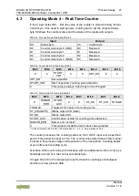
To detect static CLOCK signals, a Watchdog time has been implemented.
The default value for the time is 10 s. The time is reinitialized at each power-on.
The application can change the Watchdog time during operation via the control
byte.
This process is started by writing the respective value to output bytes D1 and D0
before the T
WD
_REQ bit is written to the control byte.
A successful parameter transfer is confirmed by the T
WD
_ACK bit in the status
byte.
Display of Invalid Watchdog Times
The range of the Watchdog timer goes from 0 to 16383 ms (0x0000 to 0x3FFF)
in steps of 1 ms per digit. Values that leave the permitted range of the Watchdog
timer are identified with 0x3FFF.
4.2.3
Set Output
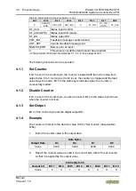
Bit 2 of the control byte sets the digital output DO.
4.2.4
Example
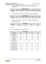
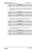
The measuring range is changed to range 2:
1.
Set the new measuring range in the control byte with bits 0 and 1
(requirement of measuring range change).
Control Byte C0
Output bit
Bit 7 Bit 6 Bit 5 Bit 4 Bit 3 Bit 2 Bit 1 Bit 0
Value
0
X
X
X
X
X
0
1
2.
Wait for feedback from the Up/Down Counter in the status byte, bits 0 and
1 (confirmation of measuring range change).
Status Byte S0
Input bit
Bit 7 Bit 6 Bit 5 Bit 4 Bit 3 Bit 2 Bit 1 Bit 0
Value
X
X
X
X
X
X
0
1
3.
After the delay time has elapsed, the current frequency value with the set
resolution is written to the input data words D0 ... D3.
Data Bytes
Input data
D3
D2
D1
D0
Value
0xXX
0xXX
0xXX
0xXX


