background image

54  Connect Devices 

WAGO I/O SYSTEM 750 XTR 


750-633/040-000 Up/Down Counter Ex i XTR 

Manual 


Version 1.1.0  


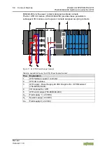
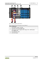
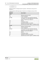
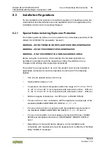
Figure 14: Power Supply Concept, Example 2 

Table 38: Legend for Figure “Power Supply Concept, Example 2“ 

Pos.  Explanation 

1  XTR fieldbus coupler / controller 
2  XTR filter module 750-626/040-000 
3  XTR filter module (750-626/040-000 or 750-624/040-001) 
4  XTR supply 750-606/040-000 “Power Supply 24 VDC Diagn for Ex i XTR 

Modules”  

5  I/O modules Ex i XTR 
6  XTR end module 


Содержание 750-633/040-000

Страница 1: ...Manual WAGO I O SYSTEM 750 XTR 750 633 040 000 Up Down Counter Ex i XTR Up Down Counter Intrinsically Safe Extreme Version 1 1 0 ...

Страница 2: ...7 84 45 55 E Mail support wago com Every conceivable measure has been taken to ensure the accuracy and completeness of this documentation However as errors can never be fully excluded we always appreciate any information or suggestions for improving the documentation E Mail documentation wago com We wish to point out that the software and hardware terms as well as the trademarks of companies used ...

Страница 3: ...ecautions 11 3 Device Description 14 3 1 View 16 3 2 Connectors 17 3 2 1 Data Contacts Local Bus 17 3 2 2 Power Jumper Contacts Field Supply 18 3 2 3 CAGE CLAMP Connectors 19 3 3 Display Elements 20 3 4 Operating Elements 20 3 5 Schematic Diagram 21 3 6 Technical Data 22 3 6 1 Device Data 22 3 6 2 Power Supply 22 3 6 3 Counters 22 3 6 4 Inputs 23 3 6 5 Output 23 3 6 6 Communication 23 3 6 7 Explos...

Страница 4: ... Removing the I O Module 47 6 Connect Devices 48 6 1 Connecting a Conductor to the CAGE CLAMP 48 6 2 Power Supply Concept 49 6 2 1 Supplementary Power Supply Regulations 52 6 3 Connection Example 55 7 Parameterizing 56 7 1 Parameterization with WAGO I O CHECK 56 7 1 1 Parameter Dialog Box 56 7 1 1 1 Toolbar 57 7 1 1 2 Parameter 58 8 Use in Hazardous Environments 59 8 1 Marking Configuration Exampl...

Страница 5: ...d in the manual for the used fieldbus coupler controller Consider power layout of the WAGO I O SYSTEM 750 XTR In addition to these operating instructions you will also need the system description Design Notes XTR Guidelines and Recommendations for Increasing Operational Safety and the manual for the used fieldbus coupler controller which can be downloaded at www wago com There you can obtain impor...

Страница 6: ...ndicates a moderate risk potentially hazardous situation which if not avoided could result in death or serious injury Personal Injury Indicates a low risk potentially hazardous situation which if not avoided may result in minor or moderate injury Damage to Property Indicates a potentially hazardous situation which if not avoided may result in damage to property Damage to Property Caused by Electro...

Страница 7: ... Font Conventions Font Type Indicates italic Names of paths and data files are marked in italic type e g C Program Files WAGO Software Menu Menu items are marked in bold letters e g Save A greater than sign between two names means the selection of a menu item from a menu e g File New Input Designation of input or optional fields are marked in bold letters e g Start of measurement range Value Input...

Страница 8: ...s All changes to the coupler or controller should always be carried out by qualified personnel with sufficient skills in PLC programming 2 1 3 Use of the 750 Series in Compliance with Underlying Provisions Fieldbus couplers controllers and I O modules found in the modular WAGO I O SYSTEM 750 receive digital and analog signals from sensors and transmit them to actuators or higher level control syst...

Страница 9: ...he user The following actions will result in the exclusion of liability on the part of WAGO Kontakttechnik GmbH Co KG Repairs Changes to the hardware or software that are not described in the operating instructions Improper use of the components Further details are given in the contractual agreements Please send your request for modified and new hardware or software configurations directly to WAGO...

Страница 10: ...lectrical and electronic equipment can be harmful to the environment and human health 2 1 4 1 2 Packaging Packaging contains materials that can be reused PPWD 94 62 EU and 2004 12 EU packaging guidelines apply throughout Europe Directives and laws may vary nationally Environmentally friendly disposal of the packaging protects the environment and allows sustainable and efficient use of resources Ob...

Страница 11: ...ate protection against UV irradiation Guarantee mechanical stability Restrict access to authorized personnel and may only be opened with tools Ensure disconnect and overcurrent protection The device is intended for installation in automation technology systems Disconnect protection is not integrated Connected systems must be protected by a fuse Provide suitable disconnect and overcurrent protectio...

Страница 12: ...rials having seeping and insulating properties The components are not resistant to materials having seeping and insulating properties such as aerosols silicones and triglycerides found in some hand creams If you cannot exclude that such materials will appear in the component environment then install the components in an enclosure being resistant to the above mentioned materials Clean tools and mat...

Страница 13: ...please ensure that environmental factors personnel work space and packaging are properly grounded Use only direct current DC for insulation testing Both the system voltage and field voltage side are capacitively coupled to the DIN rail If an I O module is mounted on the DIN rail application of an AC voltage between the DIN rail and at least one of these two potentials can lead to the destruction o...

Страница 14: ...incremented Using the operation modes Up counter with enable input the U D Gate input enables counting If the input is set I 2 1 mA counting is enabled if the input is reset I 1 2 mA counting is disabled Using operation mode Up down counter with switch output the U D Gate input determines the counting direction If the input is set I 2 1 mA the counter counts up if the input is reset I 1 2 mA the c...

Страница 15: ...040 000 Do not exceed maximum current via power contacts The maximum current available from the Power Supply 24 VDC Diagn for Ex i XTR Modules 750 606 040 000 is 1 A When configuring the system ensure that this current is not exceeded If exceeded an additional 750 606 040 000 must be used The field voltage and the system voltage are electrically isolated from each other Any configuration of the I ...

Страница 16: ... for Figure View Pos Description Details See Section 1 Marking possibility with Mini WSB 2 Status LEDs Device Description Display Elements 3 Data contacts Device Description Connectors 4 CAGE CLAMP connectors Device Description Connectors 5 Power jumper contacts Device Description Connectors 6 Release tab Mounting Inserting and Removing Devices ...

Страница 17: ...hich are available as self cleaning gold spring contacts Figure 2 Data Contacts Do not place the I O modules on the gold spring contacts Do not place the I O modules on the gold spring contacts in order to avoid soiling or scratching Pay attention to potential equalization from the environment The devices are equipped with electronic components that may be destroyed by electrostatic discharge When...

Страница 18: ...re designed as blade contacts and those on the right side as spring contacts Figure 3 Power Jumper Contacts Table 4 Legend for Figure Power Jumper Contacts Contact Type Function 1 Spring contact Potential transmission Uv for field supply 2 Spring contact Potential transmission 0 V for field supply 3 Blade contact Potential feed in 0 V for field supply 4 Blade contact Potential feed in Uv for field...

Страница 19: ...ector Function U D Gate 1 In mode 1 and 3 Enable input Gate In mode 2 Direction input Up Down In mode 4 Gate input 0 V 3 Field supply 0 V 7 8 DO 4 Digital output 24 V CLOCK 5 CLOCK input Use shielded signal lines Only use shielded signal lines for CLOCK and U D Gate inputs Only then can you ensure that the specified accuracy and interference immunity can be achieved even in the presence of interfe...

Страница 20: ...l at input Up Down Gate B Error U D Gate OFF No error at input Up Down Gate or diagnostics not active Red Error at input Up Down Gate short circuit or wire break D State DO OFF Output not active 0 V Green Output active 24 V E State CLOCK OFF No active signal at input CLOCK Green Active signal at input CLOCK F Error CLOCK OFF No error at input CLOCK or diagnostics not active Red Error at input CLOC...

Страница 21: ...WAGO I O SYSTEM 750 XTR Device Description 21 750 633 040 000 Up Down Counter Ex i XTR Manual Version 1 1 0 3 5 Schematic Diagram Figure 6 Schematic Diagram ...

Страница 22: ...upply 31 mA sensor load actuator load Current consumption system supply 25 mA Power consumption Pmax 2 2 W sensor load 8 2 mA actuator load 45 mA Power loss Pl 1 7 W sensor load 8 2 mA actuator load 45 mA Isolation 300 VAC system supply Rated surge voltage 1 kV rated surge voltage between intrinsically safe and non intrinsically safe circuits 1 5 kV EN 60079 11 Current via power jumper contacts ma...

Страница 23: ...gnal current 1 2 1 mA Input filter 10 µs Switching hysteresis 0 2 mA Open circuit voltage 8 2 VDC Input resistance 1 kΩ Short circuit current 8 2 mA 5 5 Input pulse length 10 µs Input pulse separation 10 µs 3 6 5 Output Table 11 Technical Data Outputs Number of outputs 1 Open circuit voltage 24 VDC Internal resistance Ri 285 Ω 3 6 6 Communication Table 12 Technical Data Communication Bit width 1 3...

Страница 24: ...near characteristics curve Reactance without consideration of the simultaneousness LO CO Ex ia IIC 100 mH 1 41 µF Ex ia IIB 100 mH 9 00 µF Ex ia IIA 100 mH 36 µF Ex ia I 100 mH 35 µF Reactance with consideration of the simultaneousness LO CO Ex ia IIC 100 mH 0 30 µF 20 mH 0 43 µF 1 mH 0 78 µF 0 1 mH 1 40 µF 0 001 mH 1 41 µF Ex ia IIB 100 mH 1 70 µF 20 mH 2 20 µF 1 mH 4 30 µF 0 1 mH 8 20 µF 0 001 m...

Страница 25: ...eristics curve Reactance without consideration of the simultaneousness LO CO Ex ia IIC 1 3 mH 0 091 µF Ex ia IIB 13 mH 0 719 µF Ex ia IIA 23 mH 2 369 µF Ex ia I 33 mH 3 849 µF Reactance with consideration of the simultaneousness LO CO Ex ia IIC 1 3 mH 0 0489 µF 1 mH 0 0549 µF 0 5 mH 0 0709 µF 0 1 mH 0 0919 µF 0 001 mH 0 0919 µF Ex ia IIB 13 mH 0 289 µF 10 mH 0 289 µF 1 mH 0 379 µF 0 1 mH 0 719 µF ...

Страница 26: ...hnical Data Climatic Environmental Conditions Surrounding air temperature operation 40 C 70 C Surrounding air temperature storage 40 C 85 C Relative humidity 95 Elevation above sea level without temperature derating with temperature derating max 0 m 2000 m 2000 m 5000 m 0 5 K per 100 m 5000 m Resistance to harmful substances Acc to IEC 60068 2 42 and IEC 60068 2 43 Maximum pollutant concentration ...

Страница 27: ...dule 750 633 040 000 Conformity marking CULUS UL61010 2 201 Korea Certification The following Ex approvals have been granted for the I O module 750 633 040 000 TÜV 17 ATEX 196484 X I M1 Ex ia Ma I II 3 1 G Ex ec ia Ga IIC T4 Gc II 1 D Ex ia Da IIIC IECEx TUN 17 0005X Ex ia Ma I Ex ec IIC T4 Gc Ex ec ia Ga IIC T4 Gc Ex ia Da IIIC CULUS UL 12 12 01 for Use in Hazardous Locations ...

Страница 28: ...DNV GL Temperature D cold testing at 40 C 16 h Relative humidity B Vibration B vibration testing at acceleration 5 0g EMC B Housing A LR Lloyd s Register Env 1 2 3 4 PRS Polski Rejestr Statków More information about approvals Detailed references to the approvals are listed in the document Overview Approvals WAGO I O SYSTEM 750 which you can find via the internet under www wago com DOWNLOADS Docume...

Страница 29: ...9 0 2012 A11 2013 Group II electrical equipment Equipment requirements in the types of protection EN 60079 7 2015 Electrical equipment in e type of protection with ec level of protection EN 60079 11 2012 Equipment protection by intrinsic safety i IECEx Certificates of Conformity General Requirements IEC 60079 0 ed 6 Group II electrical equipment Equipment requirements in the types of protection EC...

Страница 30: ...11 ms 1000 shocks per axis and direction half sine 25g 6 ms 1000 shocks per axis and direction half sine Environmental Requirements EN 61850 3 Achieved EN 60721 3 1 1K5 except precipitation and ice formation EN 60721 3 3 3K7 except wind driven precipitation water and ice formation EN 60870 2 2 C3 except wind driven precipitation and ice formation Shipbuilding Mechanical Climatic Environmental Cond...

Страница 31: ... 4 5 EN 60255 26 1 kV conductor conductor 2 kV conductor ground Conducted Disturbances Induced by High frequency Fields EN 61000 4 6 EN 60255 26 10 V 150 kHz 80 MHz Magnetic Fields With Electrical Frequencies EN 61000 4 8 EN 60255 26 300 A m continuous 1000 A m for 1 s Damped Oscillatory Magnetic Fields EN 61000 4 10 100 A m Voltage Dips Short term Interruptions and Voltage Fluctuations EN 61000 4...

Страница 32: ...wer Supply Units Harmonics Shipbuilding 3 Max 2 W DC 3 Veff AC 10 to 15th harmonic 10 1 for 15th to 100th harmonic 1 for 100th to 200th harmonic 1 The intrinsically safe circuits are to be implemented acc EN 60079 14 by the system installer such that the penetrating energy from other sources does not exceed the safely limited energy values in the circuit 2 To ensure proper function of inputs in th...

Страница 33: ... 60 dB µV m AV 3 GHz 6 GHz Shipbuilding Class B 80 dB µV m 50 dB µV m QP 150 kHz 300 kHz 50 dB µV m 34 dB µV m QP 0 3 MHz 30 MHz 54 dB µV m QP 30 MHz 2 GHz 24 dB µV m QP 156 MHz 165 MHz Shipbuilding Class A 80 dB µV m 50 dB µV m QP 150 kHz 30 MHz 60 dB µV m 54 dB µV m QP 30 MHz 100 MHz 54 dB µV m QP 100 MHz 2 GHz 24 dB µV m QP 156 MHz 165 MHz Conducted Emission of Interference Line Connection AC V...

Страница 34: ...lue Conducted Emission of Interference Line Connection DC Voltage EN 61000 6 3 EN 60255 26 EN 55032 Class A 79 dB µV QP 0 15 MHz 0 5 MHz 66 dB µV AV 0 15 MHz 0 5 MHz 73 dB µV QP 0 5 MHz 30 MHz 60 dB µV AV 0 5 MHz 30 MHz QP Quasi Peak Detector AV Average Detector If necessary please find different data in the section Approval regarding approval for EMC A or EMC B ...

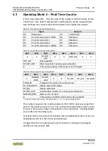
Страница 35: ... Switch Output The counter setting value to be set is stored in binary format in the 4 output bytes D0 D3 In the 4 input bytes D0 D3 the value of the counter is stored in binary format Control byte C0 is used to set and lock the counter and to set the outputs Status byte S0 shows the counter status and the status of the inputs and outputs Table 24 Process Image Operating Modes 1 and 2 Input Output...

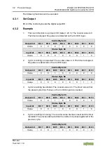
Страница 36: ...ontrol byte the counter is loaded with the 32 bit value from output bytes 0 to 3 As long as the bit is set the counter is stopped and the load value stays the same Bit 5 in the status byte indicates when the counter is successfully loaded 4 1 2 Disable Counter If bit 4 is set in the control byte counts are locked Bit 4 in the status byte shows when the counter is locked 4 1 3 Set Output Bit 2 of t...

Страница 37: ...Bit 1 Bit 0 Value 0 X 0 X X X X X 5 The set counter value then appears in the input data with the following databases D0 to D3 Data Bytes Input data D3 D2 D1 D0 Value 0x00 0x00 0x00 0x64 Count up 6 Wait for the first counting pulse and for others Data Bytes Input data D3 D2 D1 D0 No counting pulse received 0x00 0x00 0x00 0x64 1st counting pulse received 0x00 0x00 0x00 0x65 2nd counting pulse recei...

Страница 38: ... Bit 7 Bit 6 Bit 5 Bit 4 Bit 3 Bit 2 Bit 1 Bit 0 0 0 0 TWD REQ 0 SET_DO RANGE_S EL REQ1 RANGE_S EL REQ0 RANGE_SEL REQ0 Selection of the integration time and display of the measured frequency values see below RANGE_SEL REQ1 Selection of the integration time and display of the measured frequency values see below SET_DO Set output DO TWD REQ Requirement to change the Watchdog time TWD with valid data...

Страница 39: ...iods 20 Hz 16 kHz Frequency in 1 1000 Hz 2 0 1 4 periods 160 Hz 20 kHz Frequency in 1 100 Hz 3 1 0 16 periods 4 kHz 50 kHz Frequency in 1 10 Hz 4 1 1 64 periods 16 kHz 50 kHz Frequency in Hz Note the delay time when changing the frequency range When setting a new frequency range there is a delay time until valid data are read After acknowledging the new frequency range settings via the RANGE_SEL A...

Страница 40: ...83 ms 0x0000 to 0x3FFF in steps of 1 ms per digit Values that leave the permitted range of the Watchdog timer are identified with 0x3FFF 4 2 3 Set Output Bit 2 of the control byte sets the digital output DO 4 2 4 Example The measuring range is changed to range 2 1 Set the new measuring range in the control byte with bits 0 and 1 requirement of measuring range change Control Byte C0 Output bit Bit ...

Страница 41: ...is always 0 and may not be changed Table 33 Status Byte S0 Operating Mode 4 Bit 7 Bit 6 Bit 5 Bit 4 Bit 3 Bit 2 Bit 1 Bit 0 X NAMUR_ ERR START_ ACK X X ST_DO ST_U D TOGGLE TOGGLE Toggle bit for expiry of recording cycle ST_U D GATE Status output U D Gate ST_DO Status output DO START_ACK Confirmation of start for counting pulse detection NAMUR_ERR Namur error at input X This value is not defined an...

Страница 42: ...d No pulses are detected on the CLOCK input Control Byte C0 Output bit Bit 7 Bit 6 Bit 5 Bit 4 Bit 3 Bit 2 Bit 1 Bit 0 Value 0 0 1 0 0 X 0 0 Status Byte S0 Input bit Bit 7 Bit 6 Bit 5 Bit 4 Bit 3 Bit 2 Bit 1 Bit 0 Value 0 0 0 0 0 X 1 0 3 Cyclic recording has started The counter value is 0 The timer runs with at the preset cycle time Pulses on the CLOCK input are counted Control Byte C0 Output bit ...

Страница 43: ...7 Bit 6 Bit 5 Bit 4 Bit 3 Bit 2 Bit 1 Bit 0 Value 0 0 1 0 0 X 1 0 6 Cyclic recording is running The request was made to stop cyclic recording The process data provides the counter value of the previous cycle Control Byte C0 Output bit Bit 7 Bit 6 Bit 5 Bit 4 Bit 3 Bit 2 Bit 1 Bit 0 Value 0 0 0 0 0 X 0 0 Status Byte S0 Input bit Bit 7 Bit 6 Bit 5 Bit 4 Bit 3 Bit 2 Bit 1 Bit 0 Value 0 0 1 0 0 X 1 X ...

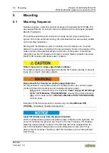
Страница 44: ...ontacts The blade contacts are sharp edged Handle the I O module carefully to prevent injury Do not touch the blade contacts Requirements for Clearances and Creepage Distances For all sections of a node that contain I O modules for Ex i use stricter require ments with regard to clearances and creepage distances apply Before such a node section the respective Power supply 24 VDC Diagn for Ex i XTR ...

Страница 45: ...s bus end module at all fieldbus nodes with the WAGO I O SYSTEM 750 XTR fieldbus couplers controllers to guarantee proper data transfer For vibration loads 4g observe the following installation instructions Use pan head screws or blind rivets at least every 60 mm 12 mm pin spacing to secure the DIN rail Make the open conductor length between strain relief and wire connection as short as possible U...

Страница 46: ...k when devices are energized High voltage can cause electric shock or burns Switch off all power to the device prior to performing any installation repair or maintenance work Temperature range applies to normal operation XTR I O modules may be operated below 20 C but not wired and or reconnected 5 2 1 Inserting the I O Module 1 Position the I O module so that the tongue and groove joints to the fi...

Страница 47: ...odule snapped in place the electrical connections for the data contacts and power jumper contacts if any to the fieldbus coupler controller or to the previous or possibly subsequent I O module are established 5 2 2 Removing the I O Module 1 Remove the I O module from the assembly by pulling the release tab Figure 9 Removing the I O Module Example Electrical connections for data or power jumper con...

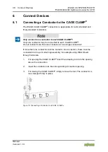
Страница 48: ...o each CAGE CLAMP Do not connect more than one conductor at one single connection If more than one conductor must be routed to one connection these must be connected in an up circuit wiring assembly for example using WAGO feed through terminals 1 For opening the CAGE CLAMP insert the actuating tool into the opening above the connection 2 Insert the conductor into the corresponding connection openi...

Страница 49: ...e required Do not exceed maximum current via power contacts The maximum current available from the Power Supply 24 VDC Diagn for Ex i XTR Modules 750 606 040 000 is 1 A When configuring the system ensure that this current is not exceeded If exceeded an additional 750 606 040 000 must be used Keep the air and creep distances between intrinsically safe segments The maximum current available from the...

Страница 50: ...equent I O modules via the power contacts designed as spring contacts Figure 11 Ex i XTR Power Supply Concept Table 34 Legend for Figure Ex i XTR Power Supply Concept Pos Explanation 1 XTR fieldbus coupler controller 2 XTR I O modules 3 XTR supply Power Supply 24 VDC Diagn for Ex i XTR Modules 750 606 040 000 4 I O modules Ex i XTR 5 XTR end module 750 600 040 000 UF1 Field supply 1 24 VDC US Syst...

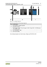
Страница 51: ...tage Categories Table 35 Legend for Figure Overvoltage Categories Pos Explanation 1 XTR fieldbus coupler controller 2 XTR filter module 3 XTR supply module Power Supply 24 VDC Diagn for Ex i XTR Modules 750 606 040 000 4 I O modules Ex i XTR 5 XTR end module Overvoltage categories and rated surge voltage see EN 61010 2 201 ...

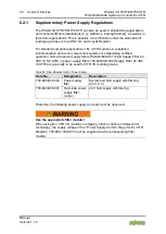
Страница 52: ...operation field side power supply filters 750 624 040 001 Field Supply Filter 24 VDC HI NC XTR or power supply filters 750 626 040 000 Supply Filter 24 VDC HI XTR are generally to be used for XTR I O module groups Table 36 Filter Modules for 24V Power Supply Item No Designation Description 750 626 040 000 Power supply filter System and field supply with filtering 24 V 0 V 750 624 040 001 Field sid...

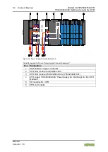
Страница 53: ... 0 Figure 13 Power Supply Concept Example 1 Table 37 Legend for Figure Power Supply Concept Example 1 Pos Explanation 1 XTR fieldbus coupler controller 2 XTR filter module 750 626 040 000 3 XTR supply Power Supply 24 VDC Diagn for Ex i XTR Modules 750 606 040 000 4 I O modules Ex i XTR 5 XTR end module ...

Страница 54: ...oncept Example 2 Table 38 Legend for Figure Power Supply Concept Example 2 Pos Explanation 1 XTR fieldbus coupler controller 2 XTR filter module 750 626 040 000 3 XTR filter module 750 626 040 000 or 750 624 040 001 4 XTR supply 750 606 040 000 Power Supply 24 VDC Diagn for Ex i XTR Modules 5 I O modules Ex i XTR 6 XTR end module ...
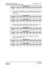
Страница 55: ... 1 0 6 3 Connection Example Figure 15 Connection Example Use shielded signal lines Only use shielded signal lines for CLOCK and U D Gate inputs Only then can you ensure that the specified accuracy and interference immunity can be achieved even in the presence of interference acting on the signal cable ...

Страница 56: ...WAGO I O CHECK 7 1 1 Parameter Dialog Box Figure 16 Parameter Dialog Box Example The parameter dialog box is divided into the following areas Titlebar with position and item number of the selected I O module information area including item number name as well as version number and version date of the I O module toolbar parameter area and statusbar ...

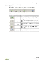
Страница 57: ...39 Legend for Figure Toolbar Symbol Designation Description Exit Closes the active window If you have changed settings you are requested for the final assumption of the values into the device Read Reads out the current settings from the attached device Write Transfers the indicated settings into the attached device Default Resets the selected I O module to the WAGO default values Help Shows the he...

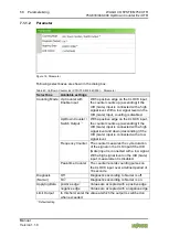
Страница 58: ...ounts up ascending if the U D Gate input is connected with a high signal level and down descending if the U D Gate input is connected with a low signal level Frequency Counter The counter measures the cycle duration of the signal on the CLK input if the U D Gate input is connected with a low signal With a high signal level on the U D Gate input measurement is disabled Peak time Counter The counter...

Страница 59: ...hazardous areas and shall be used in accordance with the marking and installation regulations The following sections include both the general identification of components devices and the installation regulations to be observed The individual subsections of the Installation Regulations section must be taken into account if the I O module has the required approval or is subject to the range of appli...

Страница 60: ...33 040 000 Up Down Counter Ex i XTR Manual Version 1 1 0 8 1 Marking Configuration Examples 8 1 1 Marking for Europe According to ATEX and IECEx Figure 19 Marking Example According to ATEX and IECEx Figure 20 Text Detail Marking Example According to ATEX and IECEx ...

Страница 61: ...Explosion group of dust T135 C Max surface temperature of the enclosure without a dust layer Dc Equipment protection level EPL Mining I Equipment group Mining M2 Category High level of protection Ex Explosion protection mark d Type of protection Flameproof enclosure I Explosion group for electrical equipment for mines susceptible to firedamp Mb Equipment protection level EPL Gases II Equipment gro...

Страница 62: ...M 750 XTR 750 633 040 000 Up Down Counter Ex i XTR Manual Version 1 1 0 Figure 21 Marking Example for Approved Ex i I O Module According to ATEX and IECEx Figure 22 Text Detail Marking Example for Approved Ex i I O Module According to ATEX and IECEx ...

Страница 63: ...ust layer Dc Equipment protection level EPL Mining I Equipment Group Mining M2 M1 Category High level of protection with electrical circuits which present a very high level of protection Ex Explosion protection mark d Type of protection Flameproof enclosure ia Ma Type of protection and equipment protection level EPL Associated apparatus with intrinsic safety electrical circuits I Explosion group f...

Страница 64: ...ates of America NEC and Canada CEC Figure 23 Marking Example According to NEC Figure 24 Text Detail Marking Example According to NEC 500 Table 43 Description of Marking Example According to NEC 500 Marking Description CL I Explosion protection gas group DIV 2 Area of application Grp A B C D Explosion group gas group op temp code T4 Temperature class ...

Страница 65: ...t protection level EPL Associated apparatus with intrinsic safety circuits for use in Zone 20 IIC Group T4 Temperature class Gc Equipment protection level EPL Figure 26 Text Detail Marking Example for Approved Ex i I O Module According to NEC 506 Table 45 Description of Marking Example for Approved Ex i I O Modules According to NEC 506 Marking Description CI I Explosion protection group Zn 2 Area ...

Страница 66: ...rk nA Type of protection ia IIIC Type of protection and equipment protection level EPL Associated apparatus with intrinsic safety circuits for use in Zone 20 IIC Group T4 Temperature class Gc Equipment protection level EPL X Symbol used to denote specific conditions of use Gases Ex Explosion protection mark nA Type of protection ia Ga Type of protection and equipment protection level EPL Associate...

Страница 67: ...ng when replacing components The product is an open system As such the product must only be installed in appropriate enclosures or electrical operation rooms to which the following applies Can only be opened using a tool or key Inside pollution degree 1 or 2 In operation internal air temperature within the range of 0 C Ta 55 C or 20 C Ta 60 C for components with extension number 025 xxx or 40 C Ta...

Страница 68: ... particular Operating DIP switches coding switches or potentiometers Replacing fuses Wiring connecting or disconnecting of non intrinsically safe circuits is only permitted in the following cases The circuit is disconnected from the power supply The area is known to be non hazardous Outside the device suitable measures must be taken so that the rated voltage is not exceeded by more than 40 due to ...

Страница 69: ...lephone networks or telecommunication cables WARNING The radio receiver module 750 642 may only be used to connect to external antenna 758 910 WARNING Product components with fuses must not be fitted into circuits subject to overloads These include e g motor circuits WARNING When installing I O module 750 538 Control Drawing No 750538 in the manual must be strictly observed Additional Information ...

Страница 70: ...xample 2 54 Figure 15 Connection Example 55 Figure 16 Parameter Dialog Box Example 56 Figure 17 Toolbar 57 Figure 18 Parameter 58 Figure 19 Marking Example According to ATEX and IECEx 60 Figure 20 Text Detail Marking Example According to ATEX and IECEx 60 Figure 21 Marking Example for Approved Ex i I O Module According to ATEX and IECEx 62 Figure 22 Text Detail Marking Example for Approved Ex i I ...

Страница 71: ...ironmental Conditions and Shipbuilding 30 Table 22 EMC Immunity to Interference 31 Table 23 EMC Emission of Interference 33 Table 24 Process Image Operating Modes 1 and 2 35 Table 25 Control Byte C0 Operating Modes 1 and 2 35 Table 26 Status Byte S0 Operating Modes 1 and 2 36 Table 27 Process Image Operating Mode 3 38 Table 28 Control Byte C0 Operating Mode 3 38 Table 29 Status Byte S0 Operating M...

Страница 72: ... 1 1 0 Table 44 Description of Marking Example for Approved Ex i I O Module According to NEC 505 65 Table 45 Description of Marking Example for Approved Ex i I O Modules According to NEC 506 65 Table 46 Description of Marking Example for Approved Ex i I O Modules According to CEC 18 attachment J 66 ...

Страница 73: ...WAGO I O SYSTEM 750 XTR 73 750 633 040 000 Up Down Counter Ex i XTR Manual Version 1 1 0 ...

Страница 74: ...WAGO Kontakttechnik GmbH Co KG Postfach 2880 D 32385 Minden Hansastraße 27 D 32423 Minden Phone 49 571 887 0 Fax 49 571 887 844169 E Mail info wago com Internet www wago com ...

Отзывы: