background image

WAGO-I/O-SYSTEM 750 

Notes about this Documentation 

750-496 8AI 0/4-20mA S.E.

Manual 

Version 

1.2.2


1.4 

Symbols 

Personal Injury! 

Indicates a high-risk, imminently hazardous situation which, if not avoided, will 

result in death or serious injury. 

Personal Injury Caused by Electric Current! 

Indicates a high-risk, imminently hazardous situation which, if not avoided, will 

result in death or serious injury. 

Personal Injury! 

Indicates a moderate-risk, potentially hazardous situation which, if not avoided, 

could result in death or serious injury. 

Personal Injury! 

Indicates a low-risk, potentially hazardous situation which, if not avoided, may 

result in minor or moderate injury. 

Damage to Property! 

Indicates a potentially hazardous situation which, if not avoided, may result in 

damage to property. 

Damage to Property Caused by Electrostatic Discharge (ESD)! 

Indicates a potentially hazardous situation which, if not avoided, may result in 

damage to property. 

Important Note! 

Indicates a potential malfunction which, if not avoided, however, will not result in 

damage to property. 

Содержание 750-496

Страница 1: ...Manual WAGO I O SYSTEM 750 750 496 8AI 0 4 20mA S E 8 Channel Analog Input 0 4 20 mA Single Ended Version 1 2 2...

Страница 2: ...E Mail support wago com Every conceivable measure has been taken to ensure the accuracy and completeness of this documentation However as errors can never be fully excluded we always appreciate any in...

Страница 3: ...Packaging 12 2 2 Safety Advice Precautions 13 3 Device Description 15 3 1 View 17 3 2 Connectors 18 3 2 1 Data Contacts Local Bus 18 3 2 2 Power Jumper Contacts Field Supply 19 3 2 3 Push in CAGE CLA...

Страница 4: ...49 7 1 1 3 2 Start Tab 50 7 1 1 3 3 Connection Tab 50 7 1 1 4 Vertical Tab Menu 51 7 1 1 4 1 Module settings Menu Item 52 7 1 1 4 2 Channel settings Menu Item 53 7 1 1 4 3 Scaling Menu Item 55 7 1 1...

Страница 5: ...IBUS DP Fieldbus Coupler Controller 750 333 0xx 000 750 833 0xx 000 81 10 1 1 2 PROFINET IO Fieldbus Coupler 750 370 750 375 025 000 750 377 025 000 81 10 1 2 Parameterization 8 AI 0 4 20 mA S E 82 10...

Страница 6: ...to these operating instructions you will also need the manual for the used fieldbus coupler or controller which can be downloaded at www wago com There you can obtain important information including...

Страница 7: ...moderate risk potentially hazardous situation which if not avoided could result in death or serious injury Personal Injury Indicates a low risk potentially hazardous situation which if not avoided may...

Страница 8: ...t this Documentation WAGO I O SYSTEM 750 750 496 8AI 0 4 20mA S E Manual Version 1 2 2 Additional Information Refers to additional information which is not an integral part of this documentation e g t...

Страница 9: ...s are marked in italic type e g C Program Files WAGO Software Menu Menu items are marked in bold letters e g Save A greater than sign between two names means the selection of a menu item from a menu e...

Страница 10: ...ll changes to the coupler or controller should always be carried out by qualified personnel with sufficient skills in PLC programming 2 1 3 Use of the 750 Series in Compliance with Underlying Provisio...

Страница 11: ...These modules contain no parts that can be serviced or repaired by the user The following actions will result in the exclusion of liability on the part of WAGO Kontakttechnik GmbH Co KG Repairs Change...

Страница 12: ...t sent to your local collection point Improper disposal of electrical and electronic equipment can be harmful to the environment and human health 2 1 4 1 2 Packaging Packaging contains materials that...

Страница 13: ...ch equipment and fixtures to authorized qualified staff only by means of specific keys or tools Ensure disconnect and overcurrent protection The device is intended for installation in automation techn...

Страница 14: ...d materials Clean tools and materials are imperative for handling devices modules Clean only with permitted materials Clean housing and soiled contacts with propanol Do not use any contact spray Do no...

Страница 15: ...or sensor types 3 6 21 mA and 4 20 mA the red error LED also indicates a wire break The meaning of the LEDs is described in the Display Elements section Power to the internal electronics is supplied v...

Страница 16: ...oller 750 841 20 750 842 19 750 843 03 750 852 01 750 871 08 750 872 04 750 873 04 750 880 04 750 881 04 750 882 04 750885 04 Fieldbus controller PFC200 750 82x 01 DeviceNet Fieldbus coupler 750 306 4...

Страница 17: ...w Pos Description Details See Section 1 Marking possibility with Mini WSB 2 Status LEDs Device Description Display Elements 3 Data contacts Device Description Connectors 4 Push in CAGE CLAMP connector...

Страница 18: ...re available as self cleaning gold spring contacts Figure 2 Data Contacts Do not place the I O modules on the gold spring contacts Do not place the I O modules on the gold spring contacts in order to...

Страница 19: ...umper Contacts Table 6 Legend for Figure Power Jumper Contacts Contact Type Function 1 Spring contact Potential transmission Uv for field supply 2 Spring contact Potential transmission 0 V for field s...

Страница 20: ...The I O module has no power jumper contacts for receiving and transmitting the earth potential Use a supply module when an earth potential is needed for the subsequent I O modules Field supply must b...

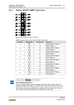
Страница 21: ...ield supply Uv 4 AI4 4 Analog input 4 Signal 24 V 12 Field supply Uv 5 AI5 5 Analog input 5 Signal 24 V 13 Field supply Uv 6 AI6 6 Analog input 6 Signal 24 V 14 Field supply Uv 7 AI7 7 Analog input 7...

Страница 22: ...bus communication Error AI1 9 OFF No error and or diagnostics deactivated or channel deactivated Red Permissible measurement range overrange and underrange short circuit general error Wire break senso...

Страница 23: ...WAGO I O SYSTEM 750 Device Description 23 750 496 8AI 0 4 20mA S E Manual Version 1 2 2 3 5 Schematic Diagram Figure 6 Schematic Diagram...

Страница 24: ...ly 3 6 3 Communication Table 11 Technical Data Communication Data width internal local bus 8 16 bit data 8 8 bit control status optional Voltage Supply Via system voltage local bus 5 VDC and power jum...

Страница 25: ...r per channel 1 25 ms per module 10 ms Resolution of measured value 12 bits 1 bit sign Measuring error at 25 C 0 1 of full scale value Temperature coefficient 0 01 K of full scale value Diagnostics Me...

Страница 26: ...erature storage 25 C 85 C Operating altitude without temperature derating 0 2000 m with temperature derating 2000 5000 m 0 5 K 100 m max 5000 m Relative humidity Max 5 95 without condensation Pollutio...

Страница 27: ...ending for 750 496 I O modules Korea Certification MSIP REM W43 AIM750 The following Ex approvals have been granted to the basic version of 750 496 I O modules CULUS ANSI ISA 12 12 01 Class I Div2 ABC...

Страница 28: ...raphic Agency BV Bureau Veritas KR Korean Register of Shipping LR Lloyd s Register Env 1 2 3 4 NKK Nippon Kaiji Kyokai PRS Polski Rejestr Statk w RINA Registro Italiano Navale The following ship appro...

Страница 29: ...and Guidelines 750 496 I O modules meet the following standards and guidelines 750 496 I O modules meet the following requirements on emission and immunity of interference EMC CE Immunity to interfer...

Страница 30: ...NE43 at a resolution of 13 bits The digitalized measured value is transmitted to the process image of the coupler controller in a data word 16 bits as input byte 0 low and input byte 1 high This valu...

Страница 31: ...2 Byte 0 Status byte CH1_S0 Byte 0 Control byte CH1_C0 Byte 1 Function of status byte Process value CH1_D0 Byte 1 Function of control byte Reserved Byte 2 Function of status byte Process value CH1_D1...

Страница 32: ...nput current is above the current lower limit configured by the user 1 The field side input current is below the current lower limit configured by the user User Overrange User limiting value overrange...

Страница 33: ...underranges and overranges refer to manufacturer range violations Table 19 Process Image Sensor Type 0 20 mA Two s Complement Representation Input current mA Numeric value Status Byte Hex Error LED B...

Страница 34: ...0 0000 0000 0000 0 000 0x0000 0 0x00 OFF 5 6 0000 1100 1100 0 000 0x0CC8 3272 0x00 OFF 7 2 0001 1001 1001 1 000 0x1998 6552 0x00 OFF 8 8 0010 0110 0110 0 000 0x2660 9824 0x00 OFF 10 4 0011 0011 0011...

Страница 35: ...392 0x00 OFF 4 0 0000 0000 0000 0 000 0x0000 0 0x00 OFF 5 6 0000 1100 0000 1 000 0x0C08 3080 0x00 OFF 7 2 0001 1000 0001 0 000 0x1810 6160 0x00 OFF 8 8 0010 0100 0010 0 000 0x2420 9248 0x00 OFF 10 4...

Страница 36: ...0x0003 3 0x41 ON Underrange 2 0 0 0000 0000 0000 0 000 0x0000 0 0x00 OFF 2 5 0000 1111 1111 1 000 0x0FF8 4088 0x00 OFF 5 0 0001 1111 1111 1 000 0x1FF8 8184 0x00 OFF 7 5 0010 1111 1111 1 000 0x2FF8 12...

Страница 37: ...0000 0000 0 000 0x0000 0 0x00 OFF 5 6 0000 1100 1100 0 000 0x0CC8 3272 0x00 OFF 7 2 0001 1001 1001 1 000 0x1998 6552 0x00 OFF 8 8 0010 0110 0110 0 000 0x2660 9824 0x00 OFF 10 4 0011 0011 0011 0 000 0...

Страница 38: ...00 OFF 4 0 0000 0000 0000 0 000 0x0000 0 0x00 OFF 5 6 0000 1100 0000 1 000 0x0C08 3080 0x00 OFF 7 2 0001 1000 0001 0 000 0x1810 6160 0x00 OFF 8 8 0010 0100 0010 0 000 0x2420 9248 0x00 OFF 10 4 0011 00...

Страница 39: ...ntacts blade contacts cannot be linked to I O modules with fewer power contacts Risk of injury due to sharp edged blade contacts The blade contacts are sharp edged Handle the I O module carefully to p...

Страница 40: ...module so that the tongue and groove joints to the fieldbus coupler or controller or to the previous or possibly subsequent I O module are engaged Figure 7 Insert I O Module Example 2 Press the I O m...

Страница 41: ...ual Version 1 2 2 5 2 2 Removing the I O Module 1 Remove the I O module from the assembly by pulling the release tab Figure 9 Removing the I O Module Example Electrical connections for data or power j...

Страница 42: ...routed to one connection these must be connected in an up circuit wiring assembly for example using WAGO feed through terminals Terminate both solid and stranded or ferruled conductors by simply pushi...

Страница 43: ...es Only use shielded signal lines for analog signals and I O modules which are equipped with shield clamps Only then can you ensure that the accuracy and interference immunity specified for the respec...

Страница 44: ...ting modes Parameterization of module channel and scaling settings Calibration of channels and adjustment of analog inputs Monitoring WAGO I O CHECK You can obtain the WAGO I O CHECK software on a CD...

Страница 45: ...dialogs for the I O module 750 496 proceed as follows 1 Right click on the I O module 2 Click the Settings menu item see following figure Figure 12 WAGO I O CHECK user interface The configuration dia...

Страница 46: ...parameterization dialog is divided into the following areas Figure 13 Parameterization Dialog for the I O Module 750 496 1 Title bar 2 Horizontal tab menu 3 Main menu 4 Vertical tab menu 5 Area of ap...

Страница 47: ...ttons on the main menu Button Function Description Connect Creates a connection to the I O module Disconnect Interrupts an existing connection to the I O module Read Reads all parameters of the curren...

Страница 48: ...plication Menu Table 26 Buttons in the application menu Button Function Description Open Opens the dialog for loading a parameter file Save Opens the dialog for saving a parameter file Help Opens the...

Страница 49: ...selecting the source directory opens 5 Select the parameter file that you want to open 6 Click Open in the standard Windows dialog 7 The parameter file opens 7 1 1 3 1 2 Save Menu Item Calibration se...

Страница 50: ...he Channel settings menu item in the vertical tab menu you can also choose the required I O module channel in the main menu Figure 18 Start Main Menu Channel Selection List The exact meaning of the in...

Страница 51: ...the individual selection options is described in the Main Menu section 7 1 1 4 Vertical Tab Menu In the vertical tab menu you can select the individual module and channel specific menu items Figure 21...

Страница 52: ...750 750 496 8AI 0 4 20mA S E Manual Version 1 2 2 7 1 1 4 1 Module settings Menu Item Save settings Click the Write or Write all button to write any settings you have made to the I O module Figure 22...

Страница 53: ...The watchdog timer is deactivated The green LEDs illuminate continuously Process value format Number format Two s complement representation Amount sign format Factory setting 7 1 1 4 2 Channel setting...

Страница 54: ...nitoring menu item under process value N A not available and under hexadecimal process value 0 20 mA Measurement range 0 20 mA 4 20 mA Measurement range 4 20 mA 3 6 21 mA NAMURNE43 Measurement range 3...

Страница 55: ...tion is deactivated and is not displayed in the status byte Show wire break The Show wire break is activated and is displayed in the status byte The Show wire break diagnosis function is deactivated a...

Страница 56: ...active according to the measurement range selected Gain Offset values can be adjusted by activating the user scaling Activating deactivating factory scaling has no effect here Scaling method is carrie...

Страница 57: ...fall within the value range 0 65535 The resolution is 1 1024 Offset Enter the Offset value for the user scaling The Offset value causes a zero offset of the process value shift along the Y axis The v...

Страница 58: ...STEM 750 750 496 8AI 0 4 20mA S E Manual Version 1 2 2 7 1 1 4 4 Calibration Menu Item Save settings Click the Write or Write all button to write any settings you have made to the I O module Figure 25...

Страница 59: ...deactivated and factory calibration is activated Gain Enter the Gain value for the user calibration The Gain value changes the gain factor of the A D raw value The value entered must fall within the...

Страница 60: ...his area an overview of all of the I O module channels are displayed individually This overview provides information about the process value of each individual I O module channel Save settings Click t...

Страница 61: ...rocess value dec Display of the process value in decimal notation If the channel is deactivated N A not available is displayed The process value is read cyclically from the I O module Process value he...

Страница 62: ...the application area 7 1 1 6 Status Messages Activate diagnostics Activate the diagnostics in the Channel settings menu item to receive status messages This area provides information about occurring...

Страница 63: ...rning x 0x42 Measurement range underflow Warning x 0x41 User defined limiting value overrange Warning x 0x04 User defined limiting value underrange Warning x 0x08 Short circuit Error x 0x50 Informatio...

Страница 64: ...information is displayed in the status bar Status indication with display of the currently executed action as text or the respective error message if an error occurs A progress bar is displayed as the...

Страница 65: ...es in the following equations have the following meaning Table 34 Variable Legend Calibrating Measured Values Variable Meaning function m Calibration gain gain factor b Calibration offset offset x1 Ac...

Страница 66: ...mple Reference current 1 y1 0 9 mA At 1 V is x1 0 915 mA 6 Apply a second 1 1 kOhm resistor in series to the same I O module channel Read the current of the measurement device and I O module Example R...

Страница 67: ...in factor The scaling offset is the offset on the y axis When these two values are input a scaled process value is yielded as the result The following general scaling equation applies y2 y1 Gain 1024...

Страница 68: ...I O module only allows one error to be indicated A dedicated bit in the status byte is assigned to each error The associated status bit is set if an error status is detected Certain errors cause multi...

Страница 69: ...rated error bit bit 5 Wire Break or bit 6 Short Circuit is set general error bit 6 General Error is set error LED ON Process value is saturated error bit bit 0 Underrange or bit 1 Overrange is set gen...

Страница 70: ...reas and shall be used in accordance with the marking and installation regulations The following sections include both the general identification of components devices and the installation regulations...

Страница 71: ...750 496 8AI 0 4 20mA S E Manual Version 1 2 2 9 1 Marking Configuration Examples 9 1 1 Marking for Europe According to ATEX and IECEx Figure 31 Marking Example According to ATEX and IECEx Figure 32 Te...

Страница 72: ...roup of dust T135 C Max surface temperature of the enclosure without a dust layer Dc Equipment protection level EPL Mining I Equipment group Mining M2 Category High level of protection Ex Explosion pr...

Страница 73: ...nvironments 73 750 496 8AI 0 4 20mA S E Manual Version 1 2 2 Figure 33 Marking Example for Approved Ex i I O Module According to ATEX and IECEx Figure 34 Text Detail Marking Example for Approved Ex i...

Страница 74: ...c Equipment protection level EPL Mining I Equipment Group Mining M2 M1 Category High level of protection with electrical circuits which present a very high level of protection Ex Explosion protection...

Страница 75: ...rica NEC and Canada CEC Figure 35 Marking Example According to NEC Figure 36 Text Detail Marking Example According to NEC 500 Table 40 Description of Marking Example According to NEC 500 Marking Descr...

Страница 76: ...n level EPL Associated apparatus with intrinsic safety circuits for use in Zone 20 IIC Group T4 Temperature class Gc Equipment protection level EPL Figure 38 Text Detail Marking Example for Approved E...

Страница 77: ...of protection ia IIIC Type of protection and equipment protection level EPL Associated apparatus with intrinsic safety circuits for use in Zone 20 IIC Group T4 Temperature class Gc Equipment protectio...

Страница 78: ...lacing components The product is an open system As such the product must only be installed in appropriate enclosures or electrical operation rooms to which the following applies Can only be opened usi...

Страница 79: ...Operating DIP switches coding switches or potentiometers Replacing fuses Wiring connecting or disconnecting of non intrinsically safe circuits is only permitted in the following cases The circuit is...

Страница 80: ...works or telecommunication cables WARNING The radio receiver module 750 642 may only be used to connect to external antenna 758 910 WARNING Product components with fuses must not be fitted into circui...

Страница 81: ...e I O 750 496 8AI 0 4 20mA SE n a 16 n a INT16 8 750 496 8AI 0 4 20mA SE RA 24 24 UINT8 INT16 PFC 750 496 8AI 0 4 20mA SE n a n a n a n a 10 1 1 2 PROFINET IO Fieldbus Coupler 750 370 750 375 025 000...

Страница 82: ...0 1 2 Parameterization 8 AI 0 4 20 mA S E Apart from the user limits the GSD file can be used to provide the I O module on the PROFIBUS DP and PROFINET IO fieldbus coupler with all operating parameter...

Страница 83: ...WAGO I O SYSTEM 750 Appendix 83 750 496 8AI 0 4 20mA S E Manual Version 1 2 2 Figure 41 Example of the 750 370 fieldbus coupler parameterization dialog...

Страница 84: ...bus couplers 750 375 025 000 and 750 377 025 000 the channel s user limits can be adjusted via GSD too On input values falling below or exceeding those limits a respective process alarm will be issued...

Страница 85: ...0 mA 4 20 mA 4 20 mA 3 6 21 mA Namur NE43 3 6 21 mA Namur NE43 Input filter 25 Hz Kanal x x 0 7 deactivated Input filter 25 Hz Checkbox deactivated activated activated Factory setting 10 1 2 2 PROFIBU...

Страница 86: ...larm and entry in the diagnostics database of the station proxy Diagnosis Measuring range violation Channel x x 0 7 0 false An violation on the respective signal channel does not lead to transmission...

Страница 87: ...spective signal channel has been activated falling below the lower or above the upper user limit leads to transmission of a process alarm No entry in the diagnostics database of the station proxy is m...

Страница 88: ...22 Module settings Menu Item View 52 Figure 23 Channel settings Menu Item View 54 Figure 24 Scaling Menu Item View 56 Figure 25 Calibration Menu Item View 58 Figure 26 Monitoring Menu Item View 60 Fi...

Страница 89: ...es 89 750 496 8AI 0 4 20mA S E Manual Version 1 2 2 Figure 41 Example of the 750 370 fieldbus coupler parameterization dialog 83 Figure 42 Example of the 750 375 025 000 and 750 377 025 000 fieldbus c...

Страница 90: ...Representation 34 Table 21 Process Image Sensor Type 3 6 21 mA NAMUR NE43 Two s Complement Representation 35 Table 22 Process Image Sensor Type 0 20 mA Amount Sign Format 36 Table 23 Process Image Sen...

Страница 91: ...Ex i I O Modules According to NEC 506 76 Table 43 Description of Marking Example for Approved Ex i I O Modules According to CEC 18 attachment J 77 Table 44 Configuration PROFIBUS DP 81 Table 45 Confi...

Страница 92: ...WAGO Kontakttechnik GmbH Co KG Postfach 2880 D 32385 Minden Hansastra e 27 D 32423 Minden Phone 49 571 887 0 Fax 49 571 887 844169 E Mail info wago com Internet www wago com...

Отзывы: