69
GM 5000EA
4
5
SW11
B_04373
1.8 Nm;
1.33 lb ft
0.1 Nm
0.07 lb ft
2
3
(1)
(4)
6
7
B_03255
SW3
0.8 Nm
SW19
SW19
B_04374
SW19
2.5 Nm
2
2
OPERATING MANUAL
EDITION 04/2016
ORDER NUMBER DOC2344499
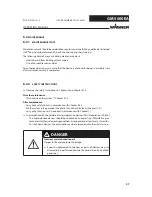
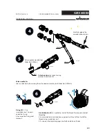
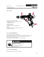
Ensure the correct
insertion position!
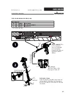
Valve needle assembly tool,
Order No. 2309368
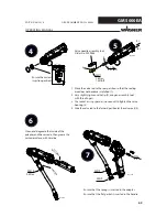
1. Move the valve rod to the rear position so that the sealing
area does not become scratched (1).
2. Very slightly tighten valve tip (2) using an assembly tool
with three fi ngers.
3. Use socket or ring spanner (no wrench) to tighten the valve
housing (3).
4. Slide the valve rod to the forward position (at the valve seat) (4).
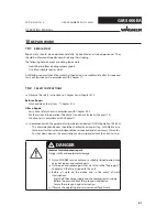
Clean and degrease the inside of the
adapter and the cascade, then grease the
cascade surface with Vaseline.
Ensure that the spring is inserted in the adapter.
Ensure that the fl at gasket is inserted in the handle.


