EN-XXX_ECOplus-Solar-Storage_MA-201026-1WA10603
5
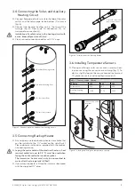
Figure 5 Connecting solar- and auxiliary heating circuit
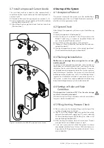
Figure 6 Installation of the backup heater
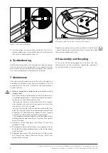
Figure 7 Placing and fixing the temperature sensors
5 Inlet for electrical
immersion heater
3.4 Connecting the Solar- and Auxiliary
Heating Circuit
●
Connect flow pipe of solar circuit to the top of the solar
coil (6) and the return pipe to the bottom (7) of same
(fig 5)
●
Connect the backup heating coil in the top of the
storage (fig 5) Flow pipe to connection (4), re-
turn pipe to connection (2)
Installation of a safety valve in the heating circuit with
a max. blow-off pressure of 3 bar!
●
Close unused connection nozzles with 1¼“ caps
3.5 Connecting Backup Heater
●
As an option, an electric backup heater is available that
can be installed in the 1½“ socket on the side (fig 6)
Please observe instructions supplied with the respec-
tive heating device
●
Laying the mains cable of the electrical heater: a heat
resistant cable (min. up to 95 °C) must be used when
laying the cable under the insulation jacket.
.
The immersion heater must only be connected to
mains after the storage tank is filled!
●
If no immersion heater is fitted, the inlet must be closed
with the supplied 1½“ plug
7 Solar circuit return
6 Solar circuit flow
4 Auxiliary heating flow
2 Auxiliary heating return
3.6 Installing Temperature Sensors
●
Placing and fixing a solar sensor and an auxilary heat-
ing sensor using the sensor terminal clamp (fig 7) To
do this, slightly loosen the sensor connection terminal
(1), place sensor (2), and re-tighten terminal (3)
Table 2 Sensor position H (mm)
ECOplus
300
400
500
Solar sensor
230
245
250
Auxilary heating
sensor
1100
1170
1255
H
1
3
2
Sensor connection
terminal


