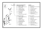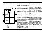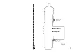
Abb. 3
Electrical connection
Disconnect the minus terminal from the battery when
wiring.
Install the electronic control module beneath the dash-
board, as near as possible to the fuse box.
Lay out the 5-core cable to the control units in the front
doors. Connect the 2-core cable to the control units of the
rear doors.
Pay attention that there is about 10 cm clearance for the
cable between the door and the beam of the vehicle. Avoid
sharp edges and bind the cable in insulation tape at
contact points.
Black cable to be fixed directly at the minus pole of batterie.
Connect the red cable with built-in fuse directly to the plus
terminal of the battery or to a continuous current line in the
fuse box.
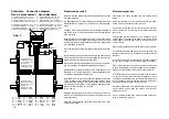
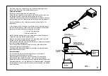
Connect the electronic control module and cable harness
(D) by connecting the 6-pole compact plug-in coupling.
Press in the cable connector of the control units according
to the wiring diagram until they engage in the correspon-
ding socket connectors of the electric cable harness.
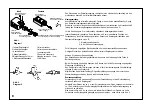
ATTENTION when connecting the control units of the rear
doors: Do not let the connectors fully engage! As a result
of a different installation of the servo units, these may have
to be changed in order to achieve the same direction of
movement of the control units (Fig. 2 and 3).
Reconnect the battery. Check that all doors can be locked
and unlocked by key from the driver’s and the front
passenger’s door.
Do not reinstall foil and door inside panelling until every-
thing is functioning properly.
Elektrischer Anschluß
Klemmen Sie den Minuspol der Batterie während der Verka-
belungsarbeiten ab.
Die Befestigung des Elektronik-Steuerteils erfolgt unter dem
Armaturenbrett, möglichst in der Nähe des Sicherungska-
stens.
Verlegen Sie die 5-adrigen Kabel zu den Steuereinheiten in
den Vordertüren, die 2-adrigen Kabel zu den Stelleinheiten
der Hintertüren.
Berücksichtigen Sie, daß zwischen der Tür und dem Holm des
Fahrzeuges etwa 10 cm Kabel Spiel bleiben müssen. Scharfe
Kanten vermeiden und das Kabel an den Berührungspunkten
mit Isolierband umwickeln.
Das schwarze Kabel direkt am Minuspol der Batterie anbrin-
gen.
Das rote Kabel mit eingebauter Sicherung wird direkt an den
Pluspol der Batterie oder im Sicherungskasten an eine Dau-
erstrom führende Zuleitung angeschlossen.
Elektronik-Steuerteil und Kabelbaum (D) durch Zusammenfü-
gen der 6-poligen Kompaktsteckkupplung verbinden.
Kabelstecker der Steuereinheiten gemäß Schaltplan bis zum
Einrasten in die entsprechenden Verbindungsstecker des
elektrischen Kabelsatzes eindrücken.
ACHTUNG beim Anschluß der Steuereinheiten der hinteren
Türen: Stecker nicht vollständig einrasten lassen! Durch
unterschiedliche Montage der Stelleinheiten müssen diese
evtl. umgewechselt werden, um die gleiche Bewegungsrich-
tung der Steuereinheiten zu erreichen.
(Fig. 2 und 3).
Batterie wieder anklemmen. Prüfen Sie, ob sich alle Türen von
der Fahrer- und Beifahrertür aus mit dem Schlüssel ver- und
entriegeln lassen.
Folie und Türverkleidung erst wieder anbringen, wenn alles
einwandfrei arbeitet.
bl
gr
br
w
sc
ro
=
=
=
=
=
=
blau
grün
braun
weiß
schwarz
rot
bl
gr
br
w
sc
ro
=
=
=
=
=
=
blue
green
brown
white
black
red
bl
gr
br
w
sc
ro
bleu
gris
marron
blanc
noir
rouge
=
=
=
=
=
=
blauw
groen
bruin
wit
zwart
rood
=
=
=
=
=
=
Steuereinheiten
Stellmotoren vorne
Servo motors, front
Moteurs de
manoeuvre avant
Stelmotoren voor
Steuereinheiten
Stellmotoren hinten
Servo motors, rear
Moteurs de
manoeuvre arrière
Stelmotoren achter
D
A
Schaltplan
Connection diagram
Plan de branchement Aansluitschema
bl
gr
br
w
sc
ro
6
Masse (-)
GND (-)
4 = externe Ste12V = ZV "auf"
4 = exetrnal c12V = ZV "open"
4 = réglage ext12V = ZV "ouvert"
4 = externe best12V = ZV "open"
9 = externe Ste12V = ZV "zu"
9 = exetrnal c12V = ZV "close"
9 = réglage ext12V = ZV "fermé"
9 = externe best12V = ZV "gesloten"
5 = externe Steuerung Masse (-) = ZV "auf"
5 = exetrnal control GND (-) = ZV "open"
5 = réglage exterieur GND (-) = ZV "ouvert"
5 = externe besteuring GND (-) = ZV "open"
10= externe Steuerung Masse (-) = ZV "zu"
10= exetrnal control GND (-) = ZV "close"
10= réglage exterieur GND (-) = ZV "fermé"
10= externe besteuring GND (-) = ZV
"gesloten"
Содержание magic lock
Страница 5: ...Abb 4 Bohrschablone Drill template Bohrung 5 mm Hole 5 mm Bohrung 5 mm Hole 5 mm 5...
Страница 10: ...10 Notizen...


