


OM 803 us – Edition 3.7 * 803b530.fm
5-27
Maintenance
Tightening the tracks
☞
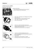
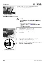
Inject grease with a grease gun through lubricating valve
A
.
☞
Check the tension is correct by lowering the machine to the ground, starting the engine,
letting it run at idling speed without any load and slowly moving the machine forward
and reverse and switching it off again. Raise the machine again with the boom.
☞
Check the tension of the tracks again.
➥
If it is not correct:
☞
Adjust again.
☞
Should the tracks still be slack after injecting more grease, replace the tracks or the
seals in the cylinders. Contact a Wacker Neuson dealer in this case.
Reducing tension
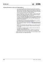
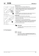
☞
Place a suitable container underneath to collect the grease.
☞
Slowly turn lubricating valve
B
one revolution counterclockwise to release the grease.
☞
Retighten the lubricating valve
B
.
➥
The grease flows out of the groove of the lubricating valve.
☞
Check the tension is correct by lowering the machine to the ground, starting the engine,
letting it run at idling speed without any load and slowly moving the machine forward
and reverse and switching it off again. Raise the machine again with the boom.
☞
Check the tension of the tracks again.
Environment!
Use a suitable container to collect the grease and dispose of it in an environ-
mentally friendly manner.
5.10 Traveling drive
Information!
The traveling drive is designed as a
maintenance-free gerotor motor
. The
hydraulic oil that flows through it lubricates and cools all moving components,
therefore an oil change is not necessary.
Fig. 219: Tightening the tracks
A
Fig. 220: Releasing grease
A
Содержание 803 dual power
Страница 32: ...1 22 OM 803 us Edition 3 7 803b110 fm Introduction...
Страница 50: ...2 18 OM 803 us Edition 3 7 803b210us fm Safety instructions Check track tension at regular intervals...
Страница 54: ...2 22 OM 803 us Edition 3 7 803b210us fm Safety instructions...
Страница 184: ...5 44 OM 803 us Edition 3 7 803b560 fm Maintenance...
Страница 200: ...6 16 OM 803 us Edition 3 7 803b610 fm Technical data...


