20
24
DigIn2 config
0
Disabled
-
1
Start/stop
-
2
AlarmReset
-
3
Rotation
direction
-
4
Test function
-
5
Ext. rotor guard
signal
-
6
Enable ext. rotor
guard
-
24
DigOut config
0
Disabled
-
Table 15 Available Holding Registers
3.4.2 0-10V control
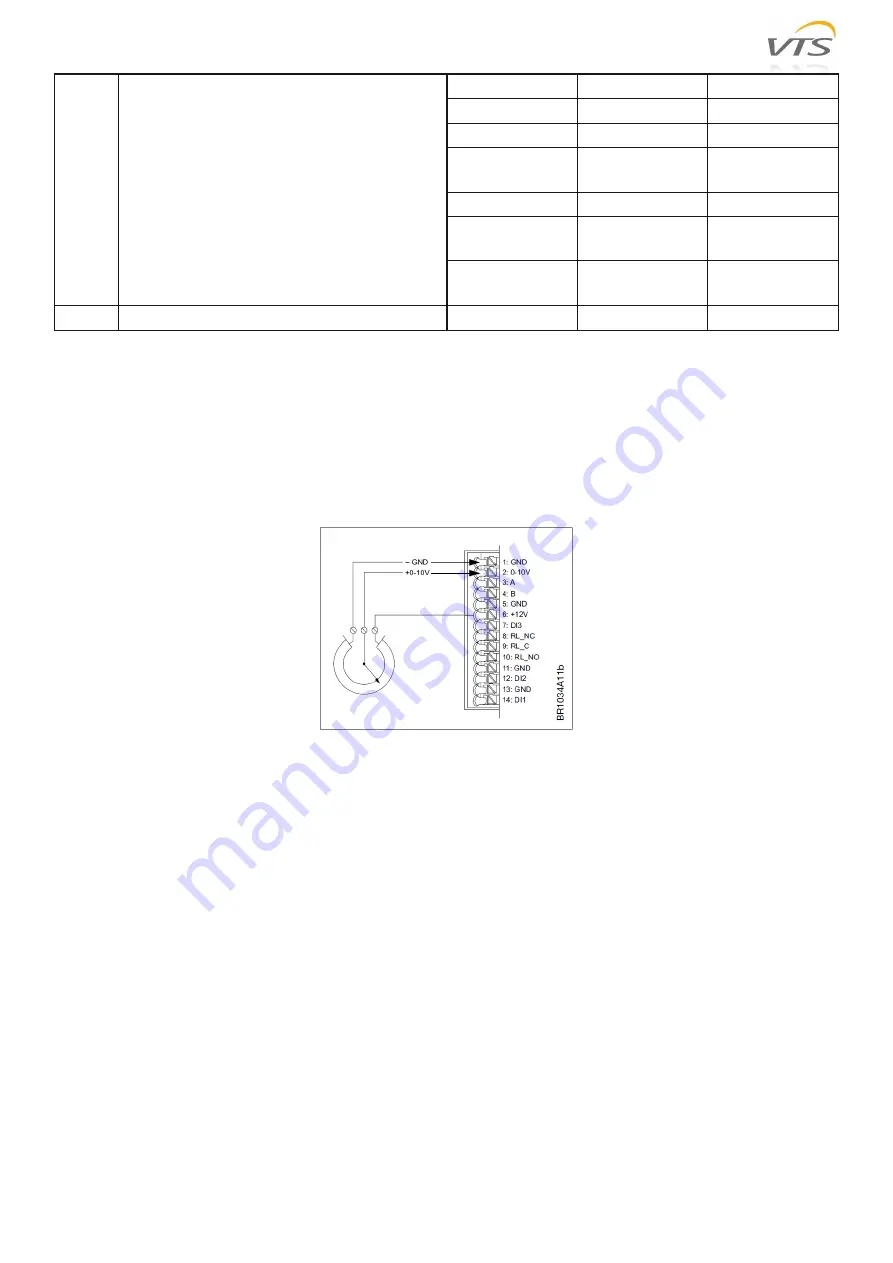
The Rotary Wheel driver is factory-configured for 0-10 V control, which is automatically deactivated when the signal
is received via the Modbus protocol, so there is no need for additional configuration when choosing analog control.
The motor starts when there is a control signal over 1.1 V and stops when control signal is less than 0.6 V. The motor
runs at maximum speed (predefined by the manufacturer for optimal work) when there is a control signal over 9.5 V.
Figure 22 Spring terminal 0-10 V control connectors using internal 12V output
3.5 Adaptation of the new OI RRG controller (SPR) to work with VTS AHU
In order to adapt the brand new RRG controller (ordered as a spare part) to work with the automation of VTS AHUs,
you should:
connect to the RRG controller using a USB-RS485 converter and a PC with software that enables reading and
writing of the Modbus slave devices registers (e.g. Modbus Poll) - the default communication parameters of
the new controller are as follows: address 79, baudrate 38400, no parity check, 2 stop bits
set the Holding Registers number 13-16 in accordance with the target communication parameters of the uPC3
controller: address 4, baudrate 9600, no parity check, 1 stop bit - see Table 15 (relevant registers are marked
in blue in the table)
Access to the registers of the rotary exchanger controller settings is done without the use of a password. The password
is also not required to save the settings after they have been changed.
To enable uPC3 - RRG OI cooperation, the RRG motor type selected on the I03 configuration screen of the uPC3
controller must be set to OI.


