


BGPS-4SI User Guide
© BGPS DVR January 2009
Rev B.
January 2009
Specifications and content are subject to change without notice.
9
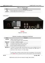
Table 2.1.1. Indication LEDs
Name
Description
HDD
LED illuminates when system is accessing the hard disk drive.
POWER
LED illuminates when the DVR unit is on.
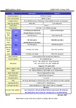
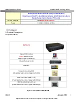
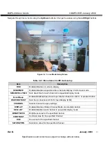
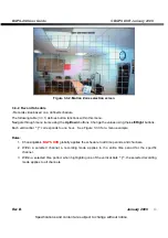
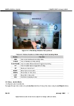
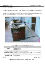
2.2. Rear Panel
BGPS-4SI
Figure2. 2.1. Rear Panel
Table 2.2.1. Connectors and Switches on Rear Panel
Name
Function
VIDEO IN
4 BNC connectors for video input
Connect camera output to Video-in (NTSC/PAL)
VIDEO OUT
1Ch VGA, 1 Ch BNC (Composite)
VIDEO
Composite video output in NTSC or PAL format
VGA
Connect to a VGA monitor 15-pin connector
LAN
RJ-45 connector for Ethernet connection
SENSOR IN
Connector for external alarm sensor/contact devices alerts the BGPS DVR and
allows it to respond to events. 4 sensors can be connected to the DVR sensor 1~4
dedicated to Video Channel 1~4 correspondingly.
Connect 2 wires to activate a sensor input to the Terminal Block on the rear panel
of the
BGPS
DVR. A ground wire from the external device to the unit ensures that


