
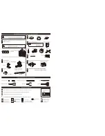

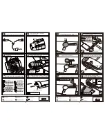


Glue the exhaust to the fuselage as below.
Cut away the surplus parts of canopy and PVC parts
carefully along the shade line.
Epoxy plies under the canopy and assemble the
canopy to fuselage with screw.
6
TP Screw (2.3x8mm)
Ply (15x15x3mm)
6
1.5mm
TP Screw (2.3x8mm)
Epoxy the PVC part to the appropriate position in wing
carefully as below.
Epoxy the PVC part to the appropriate position in wing
carefully as below.
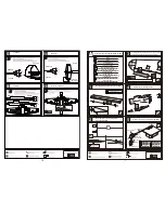
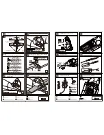
Assemble the cockpit to the fuselage and drill holes through the
ply and the wooden block in the fuselage and the cockpit,then
set blind nuts to the holes in the wooden block.
3mm
Washer (3x6mm)
2
2
Screw (3x15mm)
2
Blind Nut (3mm)
Washer (3x6mm)
Blind Nut (3mm)
Screw (3x15mm)
220mm
8mm
76
14
73
77
74
78
75
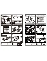
Rod (2.5x300mm)
Washer
Lock Nut (4mm )
Clevis
Clevis
Nut (3mm )
Collar (3mm)
Screw (3x10mm)
Screw (4x55mm)
2
2
Screw (4x55mm)
2
Washer
Lock Nut (4mm )
2
Clevis
2
Clevis
2
2
Screw (3x10mm)
Nut (3mm )
2
Collar (3mm)
2
Rod (2.5x300mm)
Washer(4x14mm)
2
Washer(4x14mm)
TP Screw (2.3x12mm)
1.5mm
4mm
2
4
Screw (2x10mm)
Nut (2mm )
2
Copper joiner
2
Copper ball (2mm )
Rod (2x300mm)
Ball joint
2mm
Copper joiner
Screw (2x10mm)
Nut (2mm )
Copper ball (2mm )
Nut (2mm )
120mm
2
Rod (2x300mm)
2
Clevis
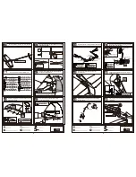
Assemble the copper joiner and link it to the
rod as illustration.
4
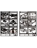
Pin hinge(24x24mm)
Flap
1mm
Make sure they are in
the right position while
installing.
Trailing
edge
Keep some space about 1mm width between
trailing edge and flap.
20mm
2mm
Install the nylon control horn and connect the linkage.
Secure the servo.Install the nylon control horn and
connect the linkage.
Rod (2.5x300mm)
Lock Nut (4mm )
Screw (3x10mm)
Nut (3mm )
Screw (4x55mm)
Washer
Clevis
Clevis
Apply instant type AB glue to flap and pin hinges.
Drill a hole to appropriate position in the flap and
epoxy the copper joiner in it as illustration.
15
o
12
15
14
11
16
13
3


