

57
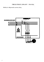
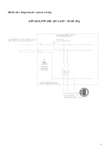
1. Power connection
The power supply must be provided by means of a line made with cable accor-
ding to present load;
Energy power distribution is composed according to wire diagram supplied.
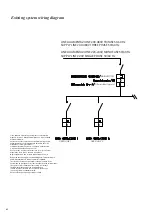
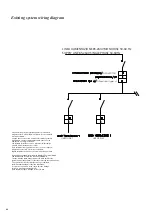
Power panel protect in MT (magnetotermic protection) line powering HVLS
fan in one single area.
Every single HVLS fans line must be protected.
Power panel must be supplied by a dedicated line protected by adequate MT
protection (minimum 20 A) and from a protection Dif-ferential A type.
The PE cable must be connected to a grounding system with impedance and
characteristics such as to ensure the proper operating of the differential pro-
tections installed in accordance with regulations about indirect contact and no
dissipation of stray currents.
Attention: line with MT+D (magnetotermic prot HVLS fan) must be
dedicated and not powered together with other devices. Cannot be derivated
from other differential A type.
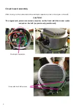
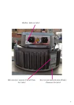
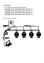
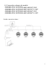
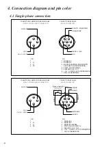
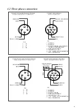
HVLS fan must be connected with its own connector to signal wire.
Togheter with power wire will be installed analogic signal wire (0-10 v ten-sion
for fan speed control) and modbus signal able to control fan and modify para-
meter through a remote PC
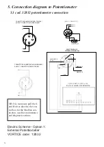
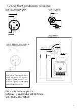
The management takes place via:
10 Kohm Potentiometer
Modbus signal through a remote PC
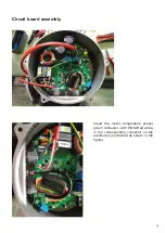
Temperature probe control unit
For analogic signal will be used a RS485 wire (2*2*AWG24 twisted and shiel-
ded).
Содержание Nordik HVSL Super Blade 110 V Series
Страница 1: ...NORDIK HVLS SUPER BLADE E SUPER BLADE 110 V Instruction booklet COD 5 571 084 939 23 07 2021 ...
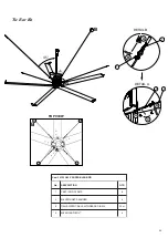
Страница 13: ...13 Fig 3 1 14 13 7 6 7 6 13 15 18 23 21 8 6 9 16 4 25 22 17 20 19 26 24 21 24 2 5 13 15 14 Bottom cap ...
Страница 25: ...25 INVERTER MOTOR ELECTRONICS QUICK CONNECTORS ...
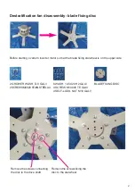
Страница 28: ...28 Destratification Fan assembly ...
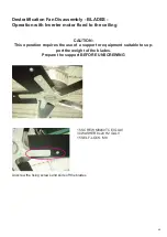
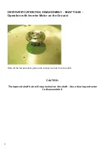
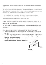
Страница 42: ...42 Destratification fan disassembly power supply Cut off the power and remove the power and signal connectors ...
Страница 56: ...56 Attachment 2 Electric connection ...
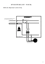
Страница 67: ...67 Multi wire diagram for system wiring SINGLE PHASE 85 264V 50 60 Hz ...
Страница 73: ...73 7 Connection Diagram with VORT T PLUS Electric Scheme Option 4 VORT T PLUS VORTICE Code 20152 ...
Страница 74: ...74 8 Connection Diagram with VORT T HCS Electric Scheme Option 3 VORT T HCS VORTICE Code 20151 ...
Страница 75: ...75 9 Connection Diagram with VORT MASTER Electric Scheme Option 3 VORT MASTER VORTICE Code 20153 ...
Страница 78: ......
Страница 79: ......


