


37
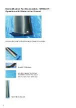
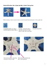
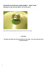
Assembling the Blade on the Destratification Fan
Blade assembly is to be carried
out with the destratification fan
positioned on the ceiling
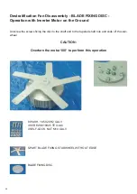
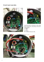
CAUTION:
The screws must be fixed with the
relative screw head on the lower
part of the blade
POSITION THE BLADE IN THE STARWHEEL
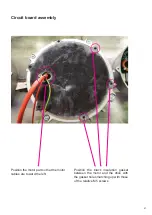
FIX WITH SCREW - WASHERS AND NUT
15 SCREW M8x60 TCEI GALV
30 WASHER 8x24 H2 GALV
15 SELF-LOCK. M8
MACHINED BLADE
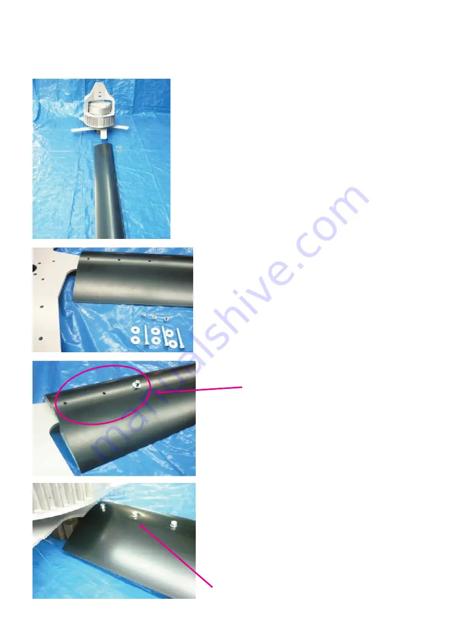
TOP PART OF THE BLADE FIXED WITH THE
SELF-LOCKING NUTS
Содержание Nordik HVSL Super Blade 110 V Series
Страница 1: ...NORDIK HVLS SUPER BLADE E SUPER BLADE 110 V Instruction booklet COD 5 571 084 939 23 07 2021 ...
Страница 13: ...13 Fig 3 1 14 13 7 6 7 6 13 15 18 23 21 8 6 9 16 4 25 22 17 20 19 26 24 21 24 2 5 13 15 14 Bottom cap ...
Страница 25: ...25 INVERTER MOTOR ELECTRONICS QUICK CONNECTORS ...
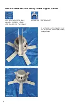
Страница 28: ...28 Destratification Fan assembly ...
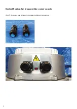
Страница 42: ...42 Destratification fan disassembly power supply Cut off the power and remove the power and signal connectors ...
Страница 56: ...56 Attachment 2 Electric connection ...
Страница 67: ...67 Multi wire diagram for system wiring SINGLE PHASE 85 264V 50 60 Hz ...
Страница 73: ...73 7 Connection Diagram with VORT T PLUS Electric Scheme Option 4 VORT T PLUS VORTICE Code 20152 ...
Страница 74: ...74 8 Connection Diagram with VORT T HCS Electric Scheme Option 3 VORT T HCS VORTICE Code 20151 ...
Страница 75: ...75 9 Connection Diagram with VORT MASTER Electric Scheme Option 3 VORT MASTER VORTICE Code 20153 ...
Страница 78: ......
Страница 79: ......


