background image

4

ITALIANO

Descrizione ed impiego

Questo prodotto è un sistema di ventilazione controllata (VMC) a doppio flusso con pompa di calore, recuperatore di calore
passivo e bypass.
Il prodotto è stato progettato per essere installato a parete, all’interno di singoli ambienti residenziali o commerciali privi di
sistemi centralizzati. L’apparecchiatura è dotata di pompa di calore e di collegamenti con l’ambiente esterno, i quali
consentono il corretto ricambio dell’aria e al tempo stesso il recupero del calore residenziale. 
Il manuale deve essere conservato per i futuri riferimenti fino allo smantellamento del prodotto. Esso è rivolto sia
all’installatore specializzato (installatori – manutentori) che all’utente finale. All’interno del manuale sono descritte le
modalità di installazione da osservare per un corretto e sicuro funzionamento dell’apparecchiatura e le modalità d’uso e
manutenzione.
In caso di vendita o passaggio dell’apparecchio ad altro utente, il manuale deve seguire l’apparecchio fino alla sua nuova
destinazione.
Prima di installare e/o utilizzare l’apparecchiatura, leggere attentamente il presente manuale di istruzioni ed in particolare
il paragrafo “Sicurezza”. Per altre avvertenze di sicurezza e riguardanti lo smaltimento dell’apparecchio fare riferimento al
foglietto allegato al prodotto. 
Il manuale va conservato con l’apparecchio e deve essere, in ogni caso, sempre a disposizione del personale qualificato
addetto all’installazione ed alla manutenzione.

Movimentazione e trasporto

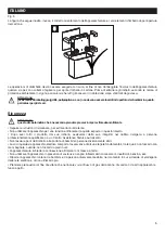
Fig. 1
Il prodotto è fornito all’interno di un imballo di cartone e protetto da supporti angolari: l’imballo è completamente riciclabile.
Durante tutte le operazioni di movimentazione e stoccaggio, l’apparecchiatura deve essere mantenuta e orientata come da
simbologia applicata sull’imballo. In caso contrario si rischia di danneggiare irrimediabilmente il compressore della pompa
di calore.

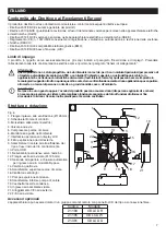
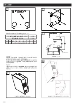
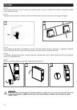
Fig. 2-3-4
Le immagini che seguono evidenziano le errate posizioni di stoccaggio e movimentazione dell’apparecchiatura. 
Queste rischiano di danneggiare irrimediabilmente il prodotto.


1


2

3


4

Содержание 45046

Страница 1: ... âÓ æ ϲV ϳ ͱ DòË âÓ ý ÅÓ í ͳ V æÓ ϲ ϳ ͳͰ VÓí Ìĉ ææÓâ í Ë ă ϲtϳ ͱͲ c Ìæ ÓÌ ϲsϳ ͲͲͰЄͲʹͰ ªĔ Ìĉ Ë ææ Ë ÓË Ì í њ V ͱʹ ªĔ Ìĉ â òß âÓ Ë ă ϲјϳ Ͷͷ VÓâí í Ë ă ϲËώϥ ϳ ͶͰ VÓí Ìĉ æÓÌÓâ þ ϰ ϲ ϳϱ Є Ë ă ý Å ʹ VÓí Ìĉ æÓÌÓâ þ ϰ ϲ ϳϱ Є Ë Ì ý Å ͳ Ë íâÓ R ϲËËϳ ͱͲ Ë Ìæ ÓÌ ϲËËϳ ͶͶͰ Ë Ìæ ÓÌ ϲËËϳ ͷͰͰ Ë Ìæ ÓÌ ϲËËϳ ͱ Ͱ V Y D JYC JD ϙ âý ĉ Ó Å Å Ìí ϙ í Å њͳ ͰͲ ͰͶ ͳ ßâ Ë Ì Ó ͱ ÓßÓ Ë ææ Ó â æíâ íÓ ϲ ÓÌæòÅ Ìĉ æò ßâÓ Óíí Ëß Ìí ϳ...

Страница 2: ... Å Ϥ Ó ßâÓ â ËË ĉ ÓÌ ÅÅ ËÓ Å í Вs D Гϙ Ì Å ß â Ó Ó Ì íÓ ÅЕ ßß â Ó ªòÌĉ ÓÌ â ÅÅ ý ÅÓ í Ë Ì Ë ß â ææ òâ â Å Óââ íí ý Ìí Å ĉ ÓÌ Å ÅÓ Å Ϛ Ë Ì Ë ĉĉ Ì Ó Å ÓÌí ËßÓ ÓÌæòË Ϥ Ó ý æò Å ĉĉ ĉ ÓÌ ÅÅ í Ëß â íòâ ÅÅЕ Ë Ìí ÅÅЕ â â ÌÌÓýÓϟ Ó æ Ì Å ĉ ÓÌ ÅÅ ÓÌ ĉ ÓÌ ĔÅíâ æ íòâ ϟ Ϙ ͳ ËÓ Å í ªòÌĉ ÓÌ Ë ÌíÓϙ Ó â ÓÓÅ Ì ϙ ÅЕ â ý ĉ í æßòÅæ ÅÅЕ æí âÌÓ ý Ì æÓæí íò í â ªâ æ â ÌÌÓýÓϚ ĔÅíâ í ÅÅ Ëßòâ í â íí Ë Ìí ËË ææ Ì Å ÅÓ Å ϟ Ó s...

Страница 3: ... DòË âÓ æ ϲV ϳ ͱ DòË âÓ ý ÅÓ í ͳ V æÓ ϲ ϳ ͳͰ VÓí Ìĉ ææÓâ í Ë ă ϲtϳ ͱͲ c Ìæ ÓÌ ϲsϳ ͲͲͰЄͲʹͰ ªĔ Ìĉ Ë ææ Ë ÓË Ì í њ V ͱʹ ªĔ Ìĉ â òß âÓ Ë ă ϲјϳ Ͷͷ VÓâí í Ë ă ϲËώϥ ϳ ͶͰ VÓí Ìĉ æÓÌÓâ þ ϰ ϲ ϳϱ Є Ë ă ý Å ʹ VÓí Ìĉ æÓÌÓâ þ ϰ ϲ ϳϱ Є Ë Ì ý Å ͳ Ë íâÓ R ϲËËϳ ͱͲ Ë Ìæ ÓÌ ϲËËϳ ͶͶͰ Ë Ìæ ÓÌ ϲËËϳ ͷͰͰ Ë Ìæ ÓÌ ϲËËϳ ͱ Ͱ V Y D JYC JD ϙ âý ĉ Ó Å Å Ìí ϙ í Å њͳ ͰͲ ͰͶ ͳ ßâ Ë Ì Ó ͱ ÓßÓ Ë ææ Ó â æíâ íÓ ϲ ÓÌæòÅ Ìĉ æò ßâÓ Óíí Ëß ...

Страница 4: ...Ë Ì Å Ϥ Ó ßâÓ â ËË ĉ ÓÌ ÅÅ ËÓ Å í Вs D Гϙ Ì Å ß â Ó Ó Ì íÓ ÅЕ ßß â Ó ªòÌĉ ÓÌ â ÅÅ ý ÅÓ í Ë Ì Ë ß â ææ òâ â Å Óââ íí ý Ìí Å ĉ ÓÌ Å ÅÓ Å Ϛ Ë Ì Ë ĉĉ Ì Ó Å ÓÌí ËßÓ ÓÌæòË Ϥ Ó ý æò Å ĉĉ ĉ ÓÌ ÅÅ í Ëß â íòâ ÅÅЕ Ë Ìí ÅÅЕ â â ÌÌÓýÓϟ Ó æ Ì Å ĉ ÓÌ ÅÅ ÓÌ ĉ ÓÌ ĔÅíâ æ íòâ ϟ Ϙ ͳ ËÓ Å í ªòÌĉ ÓÌ Ë ÌíÓϙ Ó â ÓÓÅ Ì ϙ ÅЕ â ý ĉ í æßòÅæ ÅÅЕ æí âÌÓ ý Ì æÓæí íò í â ªâ æ â ÌÌÓýÓϚ ĔÅíâ í ÅÅ Ëßòâ í â íí Ë Ìí ËË ææ Ì Å ÅÓ Å ϟ ...

Страница 5: ...VORT HRW 60 HP MONO Libretto istruzioni Instructions Booklet Livret d istructions Betriebsanleitung ƼȝɟȨ COD 5 571 084 115 22 10 2018 ...

Страница 6: ...t aux Règlements Européens 51 Structure et équipment 51 Installation 52 Fonctionnement 57 Utilisation 58 Données dimensionelles 65 Conditions de fonctionnement 65 Raccordements électriques 66 Entretien et nettoyage 68 Vor Installation und Anschluss dieses Gerätes ist diese Anleitung aufmerksam durchzulesen Vortice kann nicht für Personen oder Sachschäden zur Verantwortung gezogen werden die auf ei...

Страница 7: ...ad altro utente il manuale deve seguire l apparecchio fino alla sua nuova destinazione Prima di installare e o utilizzare l apparecchiatura leggere attentamente il presente manuale di istruzioni ed in particolare il paragrafo Sicurezza Per altre avvertenze di sicurezza e riguardanti lo smaltimento dell apparecchio fare riferimento al foglietto allegato al prodotto Il manuale va conservato con l ap...

Страница 8: ...entro Assistenza Tecnica autorizzato Non lasciare parti dell imballo alla portata di bambini o persone diversamente abili L uso di qualsiasi apparecchio elettrico comporta l osservanza di alcune regole fondamentali tra le quali non toccarlo con mani bagnate o umide non toccarlo a piedi nudi L apparecchiatura richiede la connessione all impianto di messa a terra Non utilizzare l apparecchio in pres...

Страница 9: ... caso di smontaggio dell apparecchio con strumenti appropriati o estrazione dei ventilatori l apparecchio dovrà essere preventivamente spento e disconnesso dalla rete di alimentazione elettrica L impianto elettrico cui è collegato il prodotto deve essere conforme alle norme vigenti Collegare l apparecchio alla rete di alimentazione presa elettrica solo se la portata dell impianto presa è adeguata ...

Страница 10: ...oallavitaoqualunquealtrocontestoincuiilmalfunzionamentodiunaapplicazionepossaportare alla morte o a lesioni di persone o animali o a gravi danni alle cose o all ambiente Avvertenza Nel caso in cui un guasto oppure l avaria del prodotto possano causare danni alle persone agli animali e ai beni è necessario prevedere un sistema di sorveglianza funzionale separato e dotato di funzioni di allarme al fi...

Страница 11: ...locale deve inoltre essere dotato di adeguata linea di alimentazione elettrica Collegamenti verso l ambiente esterno Fig 8 9 L apparecchiatura necessita di due condotti verso l ambiente esterno I canali consentiranno l espulsione dell aria viziata dell ambiente e il prelievo dall esterno dell aria di rinnovo Attenzione l installazione la messa in servizio e la manutenzione del prodotto devono esse...

Страница 12: ...posita piastra di supporto in acciaio fornita La parete deve essere solida e non soggetta a vibrazioni Per il fissaggio della piastra di fissaggio a parete occorre procedere come segue Fig 13 Posizionare la piastra sulla parete Con livella verificare verticalità ed orizzontalità della piastra Segnare i fori con una matita Fig 14 15 Forare in corrispondenza dei fori tracciati Dopo la foratura inser...

Страница 13: ... 17 L apparecchiatura va agganciata alla piastra inserendo prima le due alette in acciaio predisposte nella parte inferiore 13 13 14 14 L1 L2 L3 L4 L5 L6 L7 L8 L9 320 100 160 340 540 430 514 84 12 mm Viti 5x50 testa svasata Ø10 mm 6 mm Ø Tassello minimo 8 mm Prospetto forature L4 L7 L6 L3 L5 L2 L1 ø125 mm ø125 mm 15 15 Fissaggio dell apparecchiatura 16 16 Aggancio dell apparecchiatura alla staffa ...

Страница 14: ... nebulizzazione della condensa L ugello è provvisto di innesto per il tubo di collegamento alla vaschetta di raccolta della condensa Fig 21 Durante il normale funzionamento sul fondo dell apparecchiatura si raccoglie della condensa all interno di apposita vaschetta 1 2 18 18 19 19 Viti di fissaggio per ogni bocchetta 4 Ø Tassello previsto 6 mm Dettaglio vaschetta raccolta condensa Vaschetta 21 21 ...

Страница 15: ...rendo prima le due alette d acciaio nelle feritoie predisposte nella parte inferiore dell apparecchiatura Fig 26 Completare il fissaggio del pannello frontale spingendolo completamente contro l apparecchiatura portando il pannello in battuta sull apparecchiatura Fig 27 Bloccare il pannello nella parte superiore mediante due apposite viti Click 23 23 24 24 25 25 26 26 27 27 Attenzione Nella fase in...

Страница 16: ...atori e delle relative portate d aria viene prelevata l aria interna calda per riscaldare la condotta esterna fredda Nel corso della procedura di sbrinamento automatico non sarà possibile all utente modificare la velocità di funzionamento dell apparecchio Programmazione Funzionamento automatico con programmazione oraria giornaliera definibile dall utente Pompa di calore Funzionamento automatico in...

Страница 17: ...ante o decrementare il valore 6 confermare la scelta corrente con salvataggio dei dati Funzioni pannello comandi All accensione tramite pulsante il display visualizza la schermata iniziale con la velocità di funzionamento di default velocità minima NIGHT N B In generale in mancanza di input utente dopo due minuti il display torna alla schermata del logo senza salvare eventuali cambiamenti In tal c...

Страница 18: ...e Il menu principale si può visualizzare premendo nella schermata iniziale Menu principale USE MENU Con questa opzione e tramite l immissione di password nella schermata successiva si può accedere alle impostazioni di competenza dell installatore e dell utente Installatore password 023 Utente password 013 F NIGHT 25 01 18 08 07 F SILENT 25 01 18 08 07 F SILENT 25 01 18 08 07 F SILENT Ext 21 F NIGH...

Страница 19: ...he definisce la lingua dei testi del pannello Il valore di default modificabile è ENG MBUS ID E l indirizzo MODBUS del pannello comandi F MAIN MENU USE MENU ALARM SETUP INFO F PASSWORD 000 INSTALL LANGUAGE MBUS ID SETP2 TEMP SETP1 TEMP F LIFETIME F INSTALL LANGUAGE MBUS ID SETP2 TEMP F ENG F INSTALL LANGUAGE MBUS ID SETP2 TEMP F 160 16 ...

Страница 20: ...il valore di soglia della temperatura esterna al di sotto del quale si attiva automaticamente la pompa di calore per riscaldare l aria immessa all interno Il valore di default modificabile è 18 C F LIFETIME E il valore espresso in mesi di durata dei filtri Il valore di default è 12 e può essere modificato in 6 e 3 F INSTALL LANGUAGE MBUS ID SETP2 TEMP F 26 C F INSTALL SETP1 TEMP F LIFETIME F 18 C ...

Страница 21: ...la programmazione settimanale è disattivata ALARM Con questa opzione è possibile gestire tutte le possibili voci di allarme In caso di più errori questi dovranno essere gestiti uno per uno a partire dal primo verificatosi In queste situazioni viene emessa una segnalazione intermittente Alarm sulla schermata iniziale oppure i messaggi intermittenti Alarm Block OFF nel caso degli errori bloccanti Le...

Страница 22: ...NLOCK Sonda T ext Un guasto del sensore della temperatura esterna genera questo errore non bloccante Si blocca solo la pompa di calore Dopo aver risolto il problema tramite intervento dell Assistenza Tecnica è possibile resettare l errore risposta YES su CALL SERVICE N B Il sistema non effettua automaticamente la chiamata al servizio Assistenza Tecnica SETUP Con questa opzione è possibile accedere...

Страница 23: ...postazione della velocità di funzionamento su sei fasce orarie con ora di inizio e ora di fine per ogni giorno della settimana e per due intervalli predefiniti lunedi venerdi e sabato domenica Procedere come indicato nel seguito per tutti i giorni desiderati e per tutte le fasce desiderate F SETUP DATE HOUR PROGRAM F DATE HOUR MONDAY dd 29 mm 01 yy 18 hh 13 mm 49 F SETUP DATE HOUR PROGRAM F PROGRA...

Страница 24: ...o è certificato per il funzionamento negli intervalli di temperatura indicati nella tabella seguente WB Wet Bulb Bulbo Umido F MAIN MENU ALARM SETUP INFO USE MENU F S 0 9 6 0 M 0 9 6 0 CFG 6 0 F mm G mm H mm I mm 635 431 116 87 A mm B mm C mm D mm E mm 695 664 193 248 612 Raffreddamento T C T C WB Riscaldamento T C T C WB MIN MAX MIN MAX Condizioni esterne 25 35 40 5 10 5 5 Condizioni interne 23 1...

Страница 25: ...ncassato oppure a vista mediante canale esterno a parete Fig 32 Infatti la struttura dell apparecchiatura è stata progettata per consentire l ingresso dei cavi di alimentazione sia sul lato posteriore sia dall alto Fig 33 La figura che segue illustra la morsettiera di collegamento e la sua posizione 33 33 Morsettiera HMI A GND VCC B Connettore alimentazione 31 31 Ingresso cavo a parete 32 32 ...

Страница 26: ...iera come indicato nella figura che segue v Attenzione L allacciamento dell apparecchiatura deve essere eseguita da parte di personale professionalmente qualificato Attenzione La linea di alimentazione elettrica alla quale l apparecchiatura sarà collegata deve essere protetta da un adeguato interruttore magnetotermico differenziale 34 34 A VCC B A GND VCC B 33 1 33 1 230V 50Hz MAINS L PE N N L PE L...

Страница 27: ...ontaggio del filtro è sufficiente inserirlo nell apposita sede spingere il filtro fino in fondo e rimontare il coperchio di chiusura Attenzione Eventuali riparazioni dell apparecchiatura devono essere eseguite da personale qualificato Riparazioni improprie possono mettere l utente in serio pericolo Se la vostra apparecchiatura necessita di qualsiasi riparazione contattate il servizio assistenza Att...

Страница 28: ...alto mediante l apposita linguetta Per il rimontaggio del filtro è sufficiente inserirlo nell apposita sede spingerlo in giù fino in fondo e chiudere l alloggiamento Controlli annuali Almeno una volta l anno effettuare un controllo a vista delle condizioni generali dell apparecchiatura e del fissaggio a parete Pulizia Per pulire la superfice esterna dell apparecchiatura utilizzare esclusivamente u...

Страница 29: ...ment and information on how to use and maintain it In case of sale or transfer of the device to another user the manual must follow the device to its new destination Before installing and or using the equipment read this instructions manual carefully in particular the paragraph Safety For other safety and disposal information see the leaflet attached to the product The manual must be stored with t...

Страница 30: ...ot damaged If in doubt please contact a professionally qualified person or authorised Technical Assistance Centre Never leave packaging parts within reach of children or disabled persons The use of any electric device requires compliance with a few fundamental rules including never touch it with wet or humid hands never touch it when barefoot Equipment must be connected to a grounding system Do no...

Страница 31: ...ing conditions If you need to dismantle the device using appropriate tools or remove fans the device must already be switched off and disconnected from the electrical mains The electrical system to which the product is connected must comply with regulations in place Only connect the device to the mains supply electrical outlet if plant outlet capacity is suitable for its maximum power If otherwise...

Страница 32: ...r any other context in which application malfunction can lead to death or injury to persons or animals or to serious damage to property or the environment PLEASE NOTE if a possible fault or product failure can cause damage to persons animals or property a separate functional surveillance system with alarm functions is required to exclude such damage It is also necessary to prepare replacement oper...

Страница 33: ...ulation of air flows The premises must be equipped with a suitable electrical power line Connections to the outside Fig 8 9 Equipment requires two ducts to the outside The channels will allow for the expulsion of exhausted room air and the wi thdrawal from the outside of renewed air CAUTION product installation commissioning and maintenance must be performed by qualified authorised personnel Do not...

Страница 34: ...y means of a hook on a suitable steel support plate supplied The wall must be solid and not subject to vibrations Proceed as follows to fix the wall mounting plate Fig 13 Position the plate on the wall Use the tool able to verify verticality and horizontality of the metal plate Mark the holes with a pencil Fig 14 15 Drill at the traced holes After drilling insert the dowels into the wall and proce...

Страница 35: ...lf Fig 17 Equipment should be hooked to the plate first inserting the two steel fins set at the bottom 13 13 14 14 L1 L2 L3 L4 L5 L6 L7 L8 L9 320 100 160 340 540 430 514 84 12 mm 5x50 countersunk head screw Ø10 mm 6 mm Ø Minimum dowel 8 mm Drilling profile L4 L7 L6 L3 L5 L2 L1 ø125 mm ø125 mm 15 15 Fixing equipment 16 16 Hooking equipment to brackets 2 1 17 17 Drilling table See Fig 14 e 15 ...

Страница 36: ...signed to permit nozzle fixing for condensate nebulisation The nozzle is equipped with a connector for the tube that connects it to the condensate collection tray Fig 21 The system automatically check the excessive condensate collected at the bottom of the device inside a suitable tray 1 2 18 18 19 19 Fixing screws for each vent 4 Ø Expected dowel 6 mm Detail of condensate collection tray Tray 21 ...

Страница 37: ...e front cover panel The panel should be attached by inserting the first two steel fins in the slits arranged at the bottom of the equipment Fig 26 Complete front panel fixing by pushing it completely against equipment Fig 27 Once the panel has been pushed to end stop on the equipment lock it at the top by means of the two screws Click 23 23 24 24 25 25 26 26 27 27 CAUTION In the initial phase of l...

Страница 38: ...cally adjusts fan speeds and air flow parameters While the automatic de frosting cycle is in operation the user cannot change the appliance operating speed Programming Automatic operation with user definable daily time programming Heat pump Automatic heat pump operation when the temperature conditions require it and depending on the user settings USB port The outlet can be accessed by opening the ...

Страница 39: ...ne below or decreasing the value 6 Confirm the current choice and data will be saved Control panel functions Upon start up using button the display will show the home screen with the default operating speed minimum speed NIGHT Note In general in the absence of user input after two minutes the display will return to the logo screen without saving any changes In this case press to reactivate the hom...

Страница 40: ... main menu The main menu can be displayed by pressing on the home screen Main menu USE MENU With this option and by entering the password on the next screen you can access installer and user settings Installer password 023 User password 013 ENGLISH F NIGHT 25 01 18 08 07 F SILENT 25 01 18 08 07 F SILENT 25 01 18 08 07 F SILENT Ext 21 F NIGHT 25 01 18 08 07 F MAIN MENU USE MENU ALARM SETUP INFO ...

Страница 41: ... that defines the panel text language The editable default value is ENG MBUS ID This is the control panel MODBUS address F F MAIN MENU USE MENU ALARM SETUP INFO F PASSWORD 000 INSTALL LANGUAGE MBUS ID SETP2 TEMP SETP1 TEMP F LIFETIME F INSTALL LANGUAGE MBUS ID SETP2 TEMP F ENG F INSTALL LANGUAGE MBUS ID SETP2 TEMP F 160 ...

Страница 42: ... The outside temperature threshold under which the heat pump activates automatically to heat the air introduced inside The editable default value is 18 C F LIFETIME The filter duration value expressed in months The default value is 12 and can be changed to 6 and 3 F INSTALL LANGUAGE MBUS ID SETP2 TEMP F 26 C F INSTALL SETP1 TEMP F LIFETIME F 18 C F INSTALL SETP1 TEMP F LIFETIME F 12 ...

Страница 43: ...bypass is always closed and weekly programming is deactivated ALARM This option allows you to manage all possible alarm messages Multiple errors must be managed one by one starting from the first one that occurred In these situations an intermittent Alarm signal will be emitted on the home screen or intermittent messages Alarm Block and OFF will be displayed in the event of locking errors The poss...

Страница 44: ...UNLOCK T ext Probe A fault on the external temperature sensor generates this non locking error only the heat pump locks After having resolved the problem through Technical Service intervention you can reset the error answer YES for CALL SERVICE NOTE the system does not automatically call Technical Service SETUP You can access the Date and Hour setting and weekly programming with this option ENGLIS...

Страница 45: ...ccess operating speed setting for six time slots with start and end times for each day of the week and for two pre set intervals Monday Friday and Saturday Sunday Proceed as follows for all desired days and time slots ENGLISH F SETUP DATE HOUR PROGRAM F DATE HOUR MONDAY dd 29 mm 01 yy 18 hh 13 mm 49 F SETUP DATE HOUR PROGRAM F PROGRAM MONDAY TUESDAY WEDNESDAY THURSDAY FRIDAY SATURDAY SUNDAY MON FR...

Страница 46: ...in the temperature ranges shown in the table below WB Wet Bulb ENGLISH Dimensional data Fig 30 F mm G mm H mm I mm 635 431 116 87 A mm B mm C mm D mm E mm 695 664 193 248 612 Cooling T C T C WB Heating T C T C WB MIN MAX MIN MAX External conditions 25 35 40 5 10 5 5 Internal conditions 23 16 30 15 20 14 F MAIN MENU ALARM SETUP INFO USE MENU F S 0 9 6 0 M 0 9 6 0 CFG 6 0 ...

Страница 47: ... of an external wall channel Fig 32 In fact the structure of the equipment has been designed to allow the input of power cables at both the back and from above Fig 33 The figure below shows the connection terminal board and its location 33 33 Morsettiera HMI A GND VCC B Connettore alimentazione 31 31 Details of possible power cable input 32 32 Cable input from above Wall cable input HMI Terminals ...

Страница 48: ...rminal board shown in the following figure CAUTION Equipment connection must be carried out by professionally qualified personnel CAUTION The electrical power line to which the equipment will be connected must be protected by a suitable differential thermal magnetic switch 34 34 A VCC B A GND VCC B 33 1 33 1 230V 50Hz MAINS L PE N N L PE L1 N PE Mains 2 poles switch A GND VCC B ...

Страница 49: ... 36 Remove the filter by grasping the tab on it To reinstall the filter simply insert it in the corresponding housing pushing it down to end stop and reassemble the closing cover CAUTION All equipment repairs must be carried out by qualified personnel Improper repairs can put the user in serious danger If your equipment needs repair contact service assistance CAUTION beforeundertakinganymaintenance...

Страница 50: ...lter by pulling it up with the corresponding tab To reinstall the filter simply insert it in the corresponding housing pushing it down to end stop and closing housing Annual checks At least once a year perform a visual inspection of general equipment conditions and wall mounting Cleaning To clean the outside surface of equipment use only a soft clean cloth dampened with water or non abrasive or ag...

Страница 51: ...ERVENTION TIMBRO CENTRO ASSISTENZA STAMP OF TECHNICAL ASSISTANCE CENTRE CACHET SERVICE APRES VENTE TAGLIANDO INTERVENTO IN GARANZIA CERTIFICATE OF WORK PERFORMED UNDER GUARANTEE COUPON INTERVENTION SOUS GARANTIE DATA INTERVENTO DATE OF WORK DATE INTERVENTION TIMBRO CENTRO ASSISTENZA STAMP OF TECHNICAL ASSISTANCE CENTRE CACHET SERVICE APRES VENTE TAGLIANDO INTERVENTO IN GARANZIA CERTIFICATE OF WORK...

Страница 52: ...ge or modified or repaired by any person not authorised by us The correct electricity supply voltage is shown on the rating plate attached to the appliance This guarantee is normally available only to the original purchaser of theappliance but the Company will consider written applications for transfer Should any defect arise in any Vortice product and a claim under guarantee become necessary the ...

Страница 53: ...rivanti da un errato allacciamento alla rete di alimentazione elettrica o per tensione di alimentazione diversa da quella prevista per l apparecchio ovvero diversa dal limite stabilito dalle norme CEI 10 del valore nominale La presente garanzia non copre inoltre gli eventuali difetti derivanti da una cattiva manutenzione ovvero da interventi effettuati da personale non qualificato o da terzi non a...

Отзывы: