2
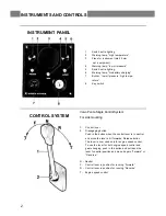
INSTRUMENT PANEL
1.
Switch, extra lighting
2.
Warning lamp, “high temperature”
3.
Place for instrument (dia 52 mm,
opt. equipment)
4.
Warning lamp, “low oil pressure”
5.
Switch, extra lighting
6.
Warning lamp, “No battery charging”
7.
Buzzer, “low oil pressure, high tempe-
rature”
8.
Key switch
CONTROL SYSTEM
Volvo Penta Single Control System
For side mounting
1.
Control lever
2.
Disengaging button
Push in the button when the control lever is in neutral
and move the lever a bit forwards. Release button.
The lever is now used only for engine speed control.
To use the lev er for both engine speed control and
gear-changing, push in the button and pull back the
lever to neutral position and move it again “Forward” or
“Reverse”.
N
=
Neutral
F
=
Control lever in position for running “Forward”
R
=
Control lever in position for running “Reverse”
T
=
Engine speed control
INSTRUMENTS AND CONTROLS


