background image

User Manual 

Stream MK3/SC2/SH65 series 

VOLUMIC • 12bis Rue Louis GARNERAY 06300 NICE • Tel: +33 (0)9 500 27 400 • Email: [email protected] • Web:www.volumic3d.com 

page |23| 


PRINTER MENU 


VOLUMIC 3D printers are equipped with a color LCD touch screen to allow control and autonomous 
printing. The touch function allows you to navigate and select/launch the functions to be performed. 


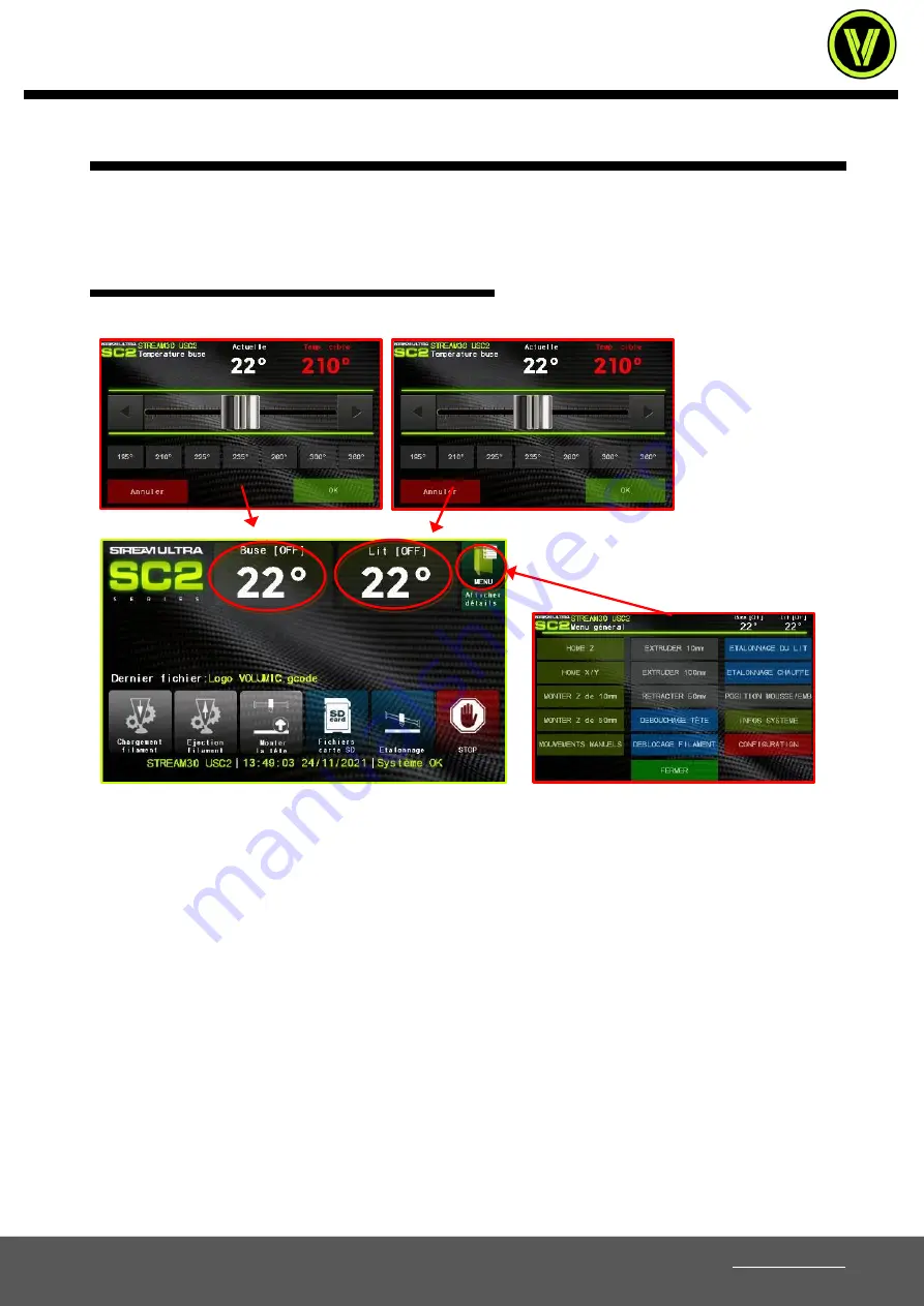
HOME SCREEN AND BRANCHES: 


(*)  The  logo  displayed  on  the 
screenshots  may  vary,  but  the 

content remains the same on all models.


On  the  home  screen  you  will  find  general  printer  information  such  as,  at  the  top,  the  nozzle(s)  and  bed 
temperatures, which you can click on to manually change the temperatures. The temperatures indicated in small 
[in square brackets] are the targets to be reached. The orange color indicates that the heating is in progress, the 
white stabilization. 
 
You will find at the bottom the system message line as well as the date and time of the system in order to date 
the impressions in the statistics. The name of the file being printed or of the last file printed is displayed above 
the main buttons, and you can click on it to relaunch this same file. 
 
Under the MENU icon, you will be able to display or not all the details of the various functions or protections in 
which you will find information on the printing such as the current number of layers, the current height and the 
times of impressions, as well as the state of the thermal protections of the machine, of the filament detector, of 
the endstops and of the network. 
 
The  "Filament  loading"  and  "Filament  ejection"  buttons  will  allow  you  to  start  the  heating/loading  cycle  and 
automatic filament ejection. The "CANCEL/STOP" button will end any current and future movement or heating, 
whether during or outside of a print. The "SD card file" button will allow you to access the files on your SD card 
in order to launch a print, and the "MENU" button to enter the sub-menu containing all the functions of the 
printer. 


Содержание STREAM MK3 Series

Страница 1: ...USER MANUAL STREAM MK3 SC2 SH65 SERIES ORIGINAL INSTRUCTIONS v1 3 April 2022 VOLUMIC 12bis Rue Louis GARNERAY 06300 NICE Tel 33 0 9 500 27 400 Email info volumic3d com Web www volumic3d com ...

Страница 2: ...FILAMENT 10 COMPRESSOR ADJUSTMENT 10 FILAMENT DETECTOR ADJUSTMENT 11 TRAY PREPARATION 12 TAKE OFF YOUR OBJECT 13 PLATE CALIBRATION 14 PRINTING IN STAND ALONE MODE SD card 18 ETHERNET SERVER 19 SIMPLIFY3D ACTIVATION PROCEDURE 20 PRINTER MENU 23 ERROR CODES 36 HEAD CHANGE PROCEDURE 37 HEAD MAINTENANCE PROCEDURE 38 USING DIFFERENT TYPES OF NOZZLES 47 FIRMWARE UPDATE 49 GOOD PRACTICES TIPS AND TRICKS ...

Страница 3: ...nge of different materials to print to meet as many needs as possible However the user remains responsible for the qualification and validation of the application of the printed object for its intended use in particular for applications in fields with strict regulations such as medical devices and aeronautics It is a free platform in terms of materials but we still recommend the use of VOLUMIC mat...

Страница 4: ...achine or the print can still cause significant damage to the machine and even to the environment So be sure to put your printer in a suitable place avoiding as many risks as possible and provide safety devices adapted to your installation Do not deposit anythingon your printer outside or inside it keep it clean and regularly clean all deposits and other waste generated by printing Do not use alco...

Страница 5: ...pecific material to know the risks Some materials can release VOCs volatile organic compounds when printed in VOLUMIC 3D printers It can cause headaches fatigue dizziness confusion nausea malaise difficulty concentrating and a feeling of intoxication The use of a filtration hood optional is strongly recommended in these cases For more information consult the SDS safety data sheet of these material...

Страница 6: ... its transport in the best possible conditions The packing procedure for a return in the best conditions is detailed in the chapter Packing instructions for your printer A return without original packaging as well as all its protections engages your responsibility and any damage or breakage during transport cannot be taken under guarantee THE START Connect your VOLUMIC printerto the mains with the...

Страница 7: ...By default access to the machine configuration menu is not password protected We recommend that you register a password as soon as the printer is installed in order to restrict access to advanced settings via MENU Configuration Security SOFTWARE TO INSTALL Connect the supplied SD card to your computer using the supplied SD reader if your computer is not equipped with one if it does not start on it...

Страница 8: ...y of your prints To use insert the short tube into the pilot hole at the bottom of the left bearing of the reel sticking out to the rear The long tube forward The reel and the guide tubes The tubes mounted Insert them fully into the holes to avoid blocking the filament in its path The tube runs backwards Insert the spool unwinding backwards to feed the filament into the short tube Run the filament...

Страница 9: ...the back 2 Screw the hinges to the frame with the 4 screws provided and a 4mm ALLEN key 3 MK3 SC2 unscrew the 2 screws of the left bearing above the machine with a 2mm ALLEN key SH65 Put the right and left cylinder supports in position on the holes of the frame insert the M3x12 screws provided 2 on each side and tighten 4 Put the cylinder support in position and insert the 2 screws provided longer...

Страница 10: ...ment through the designated hole in the filament sensor and push it until it reaches the drive wheel 2 Once the extruder is at temperature the printer emits 3 successive beeps or a sound and the drive wheel is automatically triggered While it rotates push the filament so that it engages in the drive wheel and is loaded into the print nozzle Towards the end of loading check that your material is co...

Страница 11: ...nt that these elements are consumables and must be maintained and or changed regularly in order to have reliable operation and quality prints The classic signs of a tired nozzle and or thermal barrier are recurrent filament blockages during printing It is generally advisable to acquire a second print head in order to change it quickly in the event of wear detected and not to immobilize your printe...

Страница 12: ...ry hard loads it is possible to have to tighten the compressor to 1 turn or even less Do not neglect this setting as it can result in filament jams or slippage that will cause your prints to fail FILAMENT DETECTOR ADJUSTMENT The filament detector is adjustable in sensitivity which will allow you to adapt it to your needs Hoses for example can stretch a bit during fast movements and the sensor can ...

Страница 13: ...ters such as PrintAfix 3DLAC or Dimafix It is strongly recommended to put a layer before each print to avoid any detachment which would cause your print to fail but could also damage or disrupt the machine Adhesive tapes such as 3M 2090 and Kapton or polyimide can also be used in certain cases make sure of compatibility with the printed material but the use of lacquer is much more effective and le...

Страница 14: ...shaken vigorously before spraying for 5 to 10 seconds continuously otherwise it will come out in a liquid state and not in a droplet TAKE OFF YOUR OBJECT Once printing is complete wait for the bed temperature to drop to 35 minimum If you use lacquer it will lose more and more of its adhesion below this temperature and your object should peel off quite easily if your zero point is perfectly set or ...

Страница 15: ...eft parallelism of the X axis with respect to the plate Stage 2 adjust the front rear parallelism of the head in relation to the plate Phase 3 adjust the zero point of the head in height which will be refined later on the first impressions and using the Z adjustment function of the first layer The most important thing to rememberon phases 1 2 is that the height itself does not matter here the impo...

Страница 16: ...this procedure has been completed the right left and front rear parallelism is set and the height adjustment normally has a correct starting point If you wish to refine your general zero point after a calibration simply turn the 2 left and right adjustment knobs in the same way a knob mark is equivalent to 0 05mm clockwise to mount the head anti clockwise for the descend After calibration you have...

Страница 17: ... of the threads Your zero point is perfect Channels are barely visible and the surface is well filled Result Adhesion will be good The surface finish against the board will be very smooth Your zero point is a bit too low Channels are clearly visible and are present to the touch Result The adhesion will be very strong The material that forms the channels can be dragged ripped onto the upper layer s...

Страница 18: ...ing Z COMPENSATION FUNCTION In order to correct and refine your setting more easily the VOLUMICS have a Z height compensation function on the first layer This is accessible from the printer s home screen during the printing of the first layer only via the Adjust Z button With this function you can in real time raise or lower the position of the head within a certain limit apply an offset to it in ...

Страница 19: ...with the printer or transfer the file by network if your printer is connected by Ethernet Plus standalone mode will give you a lot more information and functionality than printing via USB IMPORTANT NOTE Do not use a MicroSD card with an SD adapter these adapters tend to make false contacts very quickly and may cause your prints to fail Only use native SD cards without an adapter SD CARD FORMAT The...

Страница 20: ...hernet Interface option The machine will save the configuration then restart to establish the connection Once the connection is established the IP address of the machine will be displayed on the home page If no IP address is displayed the connection could not be established Check your Ethernet cable connections and DHCP network configuration If you have problems with the machine starting up on the...

Страница 21: ...to install only Simplify3D manually without going through the Volumic installation follow these steps otherwise use the installation package provided which will configure your computer automatically recommended 1 Identify yourself on the sitewww simplify3d comin the Account tab with the same identifiers created when registering the license On your account page go to the Download section via the le...

Страница 22: ...f print settings via the Add Ajouter button in the process block at the bottom left 11 The settings configuration dialog will open Select the profile of your 3D printer from the top drop down menu The software is now configured for your 3D printer 12 You will find in the drop down menus below the choice of materials printing qualities as well as the Show Advanced button to display all the advanced...

Страница 23: ...event the file from being read on the printer NOTE Always go throughthe Safely Remove Hardware or Eject icon to remove your SD card to avoid any loss of data not yet written to your card backup may be delayed by Windows which will result in the stop printing while the object is not finished INTERNET ACCESS FOR SIMPLIFY3D Required Simplify3D requires aonline authentication at each launch to verify ...

Страница 24: ...tem message line as well as the date and time of the system in order to date the impressions in the statistics The name of the file being printed or of the last file printed is displayed above the main buttons and you can click on it to relaunch this same file Under the MENU icon you will be able to display or not all the details of the various functions or protections in which you will find infor...

Страница 25: ...ection button becomes Pause printing which allows printing to be paused the machine must however remain powered on and warmed up The pause must empty the buffer of instructions already loaded in memory and therefore does not start immediately after pressing the button The HEAD UP button becomes the print speed multiplier Handle this parameter with care Incorrect values will cause your prints to fa...

Страница 26: ...now at what height it is and can therefore make movements that will create collisions MOUNT Z 50mm Mounts the Z axis by 50mm If the Z axis does not have its origin point defined you will be prompted to start it or skip this step Warning if the origin point Home Z is not defined the machine will not know at what height it is and can therefore make movements that will create collisions MANUAL MOVEME...

Страница 27: ...uder Use this function if after ejecting your filament it does not eject and remains stuck in the extruder This can happen when a filament sits still in the heating head for a long time which will tend to stick it to the conduit BED CALIBRATION Starts the semi automatic print bed calibration procedure see calibration chapter Carefully follow the on screen instructions to make the calibration as ac...

Страница 28: ...layed on the screenshots may vary but the content remains the same on all models Backup Stores settings in internal memory and will remain after restart or power failure Factory Settings Restores all the default parameters of all the sections as well as the PIDs that will have to be redone heater calibration These will be restored to memory but will not be saved Use the Save button to permanently ...

Страница 29: ...button of the machine If this function is deactivated the button will systematically restart the machine if pressed If activated the front button will stop all current and future actions and holding it down for more than 3 seconds will restart the machine AutoStart file Activates deactivates the proposal to launch the last file written on the SD card when inserting it Venti Auto hood Activates dea...

Страница 30: ...s The logo displayed on the screenshots may vary but the content remains the same on all models Calibration help Enables disables the display of recommendations at the start of the bed calibration Stats To SD Enables disables the writing of print statistics to the SD card Sound beeper Enables disables button notification sounds 5 Point Calibration Enables disables the 5th point in the center of th...

Страница 31: ...lay Sets the screen saver activation time when the machine is idle The watch goes as follows At standby time the screen displays the standby page and the lighting flashes slowly At the x2 delay the screen displays the moving Volumic logo and completely turns off the lighting At delay x3 the brightness of the LCD screen is divided by 5 At delay x4 the brightness of the LCD screen is divided by 9 At...

Страница 32: ... of the extruder Standby heating Activates deactivates the standby function of the extruder temperature in case of long inactivity The time for this standby is defined in the temperatures configuration Once this delay is reached when the machine is paused or waiting for a filament change the temperature will be reduced by half As soon as an action is done the machine will heat up the extruder befo...

Страница 33: ...filament The default value is 220 C Wire loading speed Defines in mm min millimeter minute the automatic filament loading speed The default is 130mm per minute Hood fan speed Sets the speed in percentage of the hood fan if installed If the Fan Auto cover is activated in the Configuration Detections menu the setting chosen by the machine will be displayed here any modification will have no effect i...

Страница 34: ...u will find the maximum speed settings for each axis as well as the acceleration and step settings per millimeter CONFIGURATION Motors Motor Direction and Enable Signal Parameter Page The logo displayed on the screenshots may vary but the content remains the same on all models Axis direction E1 being the Extruder Defines the direction of movement of an axis If it goes in the wrong direction follow...

Страница 35: ... during a print so that no one can change any settings Note the button Cancel STOP however remains active also on the front panel for security reasons Fordelete an existing password go to this page after entering it to open the configuration delete and leave the field empty then validate Remember your password and store it in a safe place If you lose it the machine will be blocked and you will hav...

Страница 36: ...d reader and prohibits printing from an SD card USB interface Enables disables the USB interface and prohibits USB control Ethernet interface Enables disables Ethernet interface and web server By activating this option the machine will restart to activate and attempt to connect to your network in DHCP by default Ethernet in DHCP Enables disables connection in DHCP mode on the network If you want t...

Страница 37: ...ature to have more leeway 15 The minimum bed temperature has been reached This may mean that the bed temperature sensor or wiring is damaged or faulty 16 The maximum safe bed temperature has been reached If the problem persists contact VOLUMIC support support volumic3d com 17 A heating error on the head has occurred If the problem persists try changing the printhead 18 A heating control error has ...

Страница 38: ...rew the head connector 3 Remove the head cable from its guides then remove the head from its housing 4 Put your new head in its housing the cables coming out from the right between the cooling duct and the fan then put the head cover back in place and tighten the 2 knobs fully Note the sock is not mandatory but will keep your unit head cleaner over time However the sock should never be used above ...

Страница 39: ...urns in the event of carelessness or incorrect handling Wearing safety gloves is recommended for all manipulations of the head or the plate The execution of this procedure remains at your own risk be very careful Complete Gen3 head without cable Elements and parts of the Gen3 head Tube blocking end piece End cap clips for blocking Fixing block Body assembly screws M2x6 cooling body Thermal barrier...

Страница 40: ...hase for tightening Do one or two loads of filament with ULTRA purge to remove any residue eject it and let the head cool Wear safety gloves to avoid any risk of burns 1 Unscrew the head cover using its two front knobs 2 Release the head cover and take the head out of its housing 3 If the head has a protective sock remove it This is imperative otherwise it will melt Position the head so that it ha...

Страница 41: ...o that the whole head does not continue to heat 7 Screw the new nozzle onto the block Caution do not touch the head with bare hands it is still very hot until contact is made 8 Return the head to 360 C 290 C on MK3 Be careful not to touch the heater block and the head in general under penalty of serious burns 9 Once at temperature hold the heating block with a spanner multi grip by the sides oppos...

Страница 42: ...ing the cables coming out from the right between the cooling duct and the fan then put the head cover back in place and tighten the 2 knobs fully 12 Once everything is reassembled and tightened launch a heater calibration from the menu For any modification on a head or a change of element this function must be launched before any printing in order to precisely adjust the algorithm PID of heating w...

Страница 43: ...lip from the filament guide tube Capricorn XS dark blue and push the tip in with a finger at the same time removing the tube from its housing 2 Use a 1 5mm Allen key or screwdriver to unscrew the 2 clamping screws of the fixing block 3 Once the clamp block is removed check and clean the filament hole entrance shown in red in the image for any obstructions 4 If necessary unclog the duct using a 1 8...

Страница 44: ...rection the tube must be inserted on the flat side and not chamfered The chamfer is on the outside to receive the filament 7 Insert the tube fully and keeping it well pressed with one finger raise the locking tip with the other hand 8 Continue to hold the tube with a finger and insert the locking clip under the tip to completely immobilize the tube Once reassembled the tube should have no play The...

Страница 45: ...and therefore quite fragile Use tools that are in good condition or risk damaging the head of the screw and making it very difficult to disassemble 2 Gently release the heating block from the cooling body The small connection tubes can remain on the heating block like here or on the cooling body it does not matter 3 Remove the 4 small junction tubes by hand pliers could damage them 4 Remove the th...

Страница 46: ...ill be damaged very quickly if you force too much 7 Raise the heat shield from the barrier to the base of the heater block 8 Insert the 4 junction tubes on the heating block fully pushed in by hand 9 Position the heatsink to align the screw holes with those in the heater block 1 then carefully insert the heatsink thermal barrier into the heatsink until it meets the joints 10 Position the 4 junctio...

Страница 47: ...ssembly does not move Check that the heater block is well aligned with the cooling body then insert the 2 M1 5 screws andscrew them gradually in turn Do not completely tighten one screw then the other this could deform your thermal barrier 12 Tighten the screws barely more than contact 0 5Nm max No need to tighten hard you risk damaging the screw heads and threads You can now reassemble your nozzl...

Страница 48: ...y good thermal characteristics it will give very good impressions at any temperature and will be able to support larger flows of materials Its hard nickel coating also gives it increased resistance and therefore a much longer life Its increased resistance will also be able to withstand occasional impressions of lightly loaded materials The Must of nozzles for unloaded Thermal performance Resistanc...

Страница 49: ...ut the different models offered If you change nozzle diameter you will need to change your slicing settings in your software to match For Simplify3D open your process window and in the Extruder tab in advanced mode modify the diameter with the Nozzle diameter value to match that of your mounted nozzle Remember that in the case of INOX or Steel nozzles you will have to increase the temperature sign...

Страница 50: ...ate the graphics To perform the update follow these steps Visit the siteSUPPORT VOLUMICin the section Firmware Updates to the following address http support printer 3d volumic com Download the Firmware update file for your printer model WARNING Be sure to choose the file that corresponds to your machine A bad file can cause major malfunctions The files present in the archive are Engine firmware fi...

Страница 51: ...ct the Micro SD card and start the update Note If the update does not start or a card file error is displayed it is possible that the Micro SD card is not compatible Try another Micro SD card if possible from another brand and not too high capacity E Once the update is complete remove the Micro SD card then turn off the machine Now you need to do the Core update NOTE The GFX update is also possibl...

Страница 52: ...xt Note the COM15 port on the illustration below is given as an example the number of your COM port may vary choose the one corresponding to your printer Note 2 make sure that the chosen port corresponds to your printer Bluetooth accessories for example also create COM ports and will appear in the list E Then choose the downloaded Core firmware file file extension bin and click Next F Click on Fla...

Страница 53: ... bearings or belts and reduce the precision of your machine or even cause breakage or premature wear Perform a bed calibration more for safety each time the machine is moved This one will only take you a few minutes and will ensure reliable and hassle free printing Never spray adhesion lacquer inside your machine Take out your glass ceramic tray and apply your hairspray outside the machine The lac...

Страница 54: ...t accept residue from other materials passing through during printing and may clog Ideally a head dedicated to the hose remains the most effective Nozzles below 0 4mm will make printing even more finicky so it s not recommended for hoses Add 5 10 C more to the nozzle temperature if you still have too much jam Do not use PTFE guide like the one on the cover for example the hose must be on a central...

Страница 55: ...n of the drive pulley that it is still well sharpened the teeth clean and free of jams The tightening of the extruder motor screws and the extruder in general so that nothing comes loose The condition of the compressor no cracks or deformation Also check the head fans These must turn perfectly without the slightest cut or micro cut A poorly cooled head will certainly cause filament blockages belts...

Страница 56: ... may accumulate inside These are quite dangerous for the belts and bearings if they were to get caught in them Also blow the inlets of the fans to evacuate the accumulated dust motors electronic box power supply and of course clean blow regularly the drive of the extruder to prevent it from accumulating too much dust and waste which will reduce the grip on the filament Never spray lacquer inside t...

Страница 57: ... see photo below Loosen the 4 side screws of the front Y motor 1 using a 2 5mm Allen key just 2 turns are enough then screw in to tighten or unscrew to loosen the adjustment screws behind the motor 2 Once the correct tension has been obtained firmly tighten the 4 side screws of the motor 1 A correctly tensioned belt must be quite rigid but must still be able to be pressed by putting your finger on...

Страница 58: ...a 2 5mm Allen key just 2 turns are enough then screw to tighten or unscrew to loosen the adjustment screws in front of the motor 1 Once the correct tension has been obtained firmly tighten the 4 motor support screws 2 SH65 Belt tension adjustment X width Adjustment of the X belt tension is done via the X motor located on the left bearing Loosen the 4 screws of the motor below 2 using a 2 5mm Allen...

Страница 59: ... Manager branch device You can also press the WINDOWS R key and in the Run box type the instruction mmc devmgmt msc to open Device Manager 2 In Device Manager look for the Ports COM and LPT branch As you unfold it look for the line labeled USB Serial Device COMx At the end of the line is indicated the COM port on which your printer was installed COM followed by a number 3 Remember this port or wri...

Страница 60: ...ickness nozzle 0 4mm 0 01mm Maximum heating bed temperature 100 C Maximum print nozzle temperature 300 C SC2 machine parameters Connection COM PORT serial COM port speed 250000 baud Direction of origin X Y and Z Minimum Print area width 300mm Print area depth 200mm Print area height 310mm Number of extruder 1 Original nozzle size 0 4mm Filament size 1 75mm Maximum layer thickness nozzle 0 4mm 0 3m...

Страница 61: ...ise generally noted without cover about 70db Technical characteristics SC2 Power supply 100 240V 12A 6A 47 63Hz Idle power consumption 20W Power consumption in printing 700W Dimensions L54cm H50cm D48cm Weight 32Kg Airborne noise generally observed without cover about 72db Technical characteristics SH65 Power supply 100 240V 12 8A 7 8A 47 63Hz Idle power consumption 25W Power consumption in printi...

Страница 62: ...400 Email info volumic3d com Web www volumic3d com page 61 ELECTRICAL DIAGRAMS The electrical diagrams below are given as an indication for troubleshooting purposes in good conditions Any intervention is at your own risk and will invalidate the product warranty if it is still subject to it STREAM30 MK3 ...

Страница 63: ...User Manual Stream MK3 SC2 SH65 series VOLUMIC 12bis Rue Louis GARNERAY 06300 NICE Tel 33 0 9 500 27 400 Email info volumic3d com Web www volumic3d com page 62 STREAM30 SC2 ...

Страница 64: ...User Manual Stream MK3 SC2 SH65 series VOLUMIC 12bis Rue Louis GARNERAY 06300 NICE Tel 33 0 9 500 27 400 Email info volumic3d com Web www volumic3d com page 63 STREAM SH65 ...

Страница 65: ...son authorized to compile the technical file Gerard Luppino 12b rue Louis Garneray 06300 NICE France Declares that the new machines designated below VOLUMIC Fused Deposition Modeling 3D printer model SH65 VOLUMIC Fused Deposition Modeling 3D printer model STREAM30 PRO MK3 VOLUMIC Fused Deposition Modeling 3D printer model STREAM30 ULTRA SC2 Are compliant To the regulatory provisions defined by app...

Страница 66: ...ww volumic3d com page 65 PACKING INSTRUCTIONS Here are the instructions that must be followed to ensure that your machine is as secure as possible for transport IMPORTANT Only return the machine itself without any accessories cables or the like not even the glass plate Any accessory present with the machine will not be returned STEP 1 ...

Страница 67: ... volumic3d com Web www volumic3d com page 66 Plug in and turn on your VOLUMIC printer Do a HOME Z then go up 100mm Turn off and unplug your VOLUMIC printer 2ND STEP Insert under the extruder the protective foam No 3 the widest part of the top towards the front of the machine and the groove in the axis of the bottom ...

Страница 68: ... page 67 STEP 3 MK3 and SC2 only Insert the rear bed blocking foam No 2 as in the image below at the rear of the machine the notch fitting on the bed STEP 4 MK3 and SC2 only Insert the front bed blocking foam No 1 as shown in the image below at the front of the machine the front notch fitting on the bed and the angle cut to release the screen assembly ...

Страница 69: ...leave any accessories cables or trays in or with the machine STEP 5 Put four foams of angles in each corner of the carton at the bottom put the machine in the carton resting on the four foams then put the other 4 angles in the other direction on the top of the machine and close the carton tightly Warning If you no longer have the original packaging please contact your reseller or Volumic a new pac...

Страница 70: ...ies VOLUMIC 12bis Rue Louis GARNERAY 06300 NICE Tel 33 0 9 500 27 400 Email info volumic3d com Web www volumic3d com page 69 VOLUMIC 3D PRINTERS MADE IN FRANCE VOLUMIC 2022 VOLUMIC 12b rue Louis Garneray 06300 Nice France 33 9 500 27 400 ...

Отзывы: