


Owner’s Manual #513642 Rev.4
10
CC Model Machines
4
Connect the refrigeration lines from the line sets
to the machine. Access the machine from the left
or right service panel. The refrigeration system
has a charge of dry nitrogen. Use caution when
connecting the lines. Connect the suction line fi rst
then connect the liquid line. Run the refrigeration
lines under the machine. There is approximately 6”
of clearance between machine and the fl oor. The
stainless steel legs are adjustable and can raise
the machine up to 7” off the fl oor if necessary.
Wrap the suction solenoid in a cold wet rag when
soldering to prevent damage to the solenoid. Also,
be aware of the electrical conduit inside custard
machine while soldering the refrigeration lines. A
liquid line dryer is supplied with the machine and
should be the last connection made in the system.
Use good piping techniques to keep the system
clean. Do not leave the lines open and exposed
for a long period.
5
After fi nishing the refrigeration connections,
connect power to the machine. Refer to “B. Running
Electrical Lines” for the proper procedures. Check
the rotation of the auger shaft. When looking at
the machine from the front, the shaft needs to
turn counterclockwise. If the shaft is turning the
wrong direction, shut off power to the cylinder and
switch the L1 and L3 wires. Check rotation again to
verify the shaft is rotating counterclockwise. Once
verifi ed, tighten the screws on the electrical box
cover.
If the machine is single phase and the auger shaft
rotation is clockwise, then complete one of the
following procedures. Check rotation after each
procedure.
A. Change the T1 and T3 output leads going to
the motor from the drive.
B. Change the leads inside the motor electrical
box.
6
Condensing units ship from the factory with 20
lbs of R-404A for up to a 50’ line set. Add 1 lb of
refrigerant for every 10’ increase to the line set.
Line set max 100’. Use good refrigeration practices
to add additional charge to the system if needed.
Make sure the suction solenoid is energized and
that the shut off valves are open.
F. RUNNING PRODUCT AND SETTING PRESSURES
FOR THE CUSTARD MACHINE
NOTE
Complete the Custard Machine Start-Up and Train-
ing Checklist located with the spare parts kit or in
the back of this manual and send it to Stoelting.
1
Remove all spare parts from the hopper before
running product. Unwrap the parts and check for
damage. Refer to the list in the back of this manual
to make sure no parts are missing. The cylinders
need to be under a load to set the pressures.
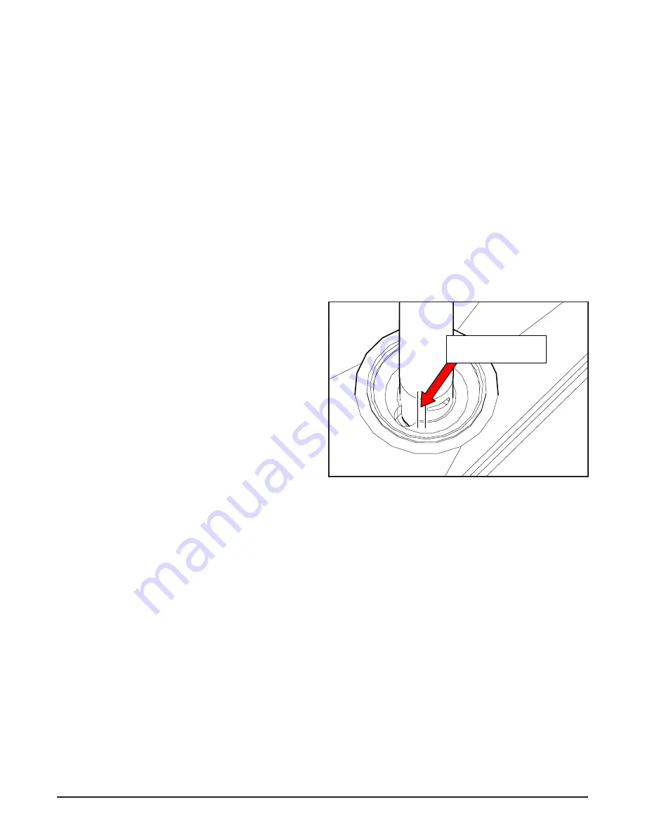
2
Install the fl ow valve and rotate it so the cutout
is about 3/32” from the cutout in the hopper (see
below). Fully close the fl ow control knob. Install
the fl ow rod. If the fl ow rod cannot be installed
without moving the fl ow valve, loosen the locknut
on the rod and adjust it. Make sure both rod ends
lay fl at, then tighten the locknut.
3
Disassemble, clean and sanitize each freezing
cylinder. Refer to the Section 3 for proper
instructions.
Approximate width
of nickel (ideally 3/32")
Approximate width
of nickel (ideally 3/32")
Содержание Stoelting CC Series
Страница 1: ...CC Model Machines OPERATORS MANUAL Manual No 513642 Rev 4 A VOLLRATH DIVISION...
Страница 2: ......
Страница 6: ......
Страница 12: ...Owner s Manual 513642 Rev 4 6 CC Model Machines...
Страница 18: ...Owner s Manual 513642 Rev 4 12 CC Model Machines...
Страница 32: ...Owner s Manual 513642 Rev 4 26 CC Model Machines...
Страница 36: ...Owner s Manual 513642 Rev 4 30 CC Model Machines...