background image

21

6.17

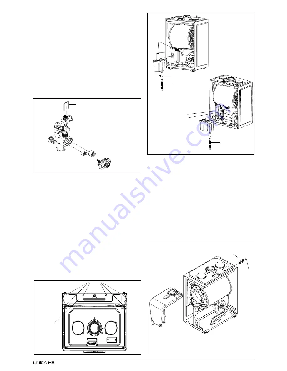
AUTOMATIC BY-PASS & DHW NON-RETURN
VALVE (fig. 32)

Carry out component removal procedure as de-
scribed in 6.4.
Remove the locking pin 

(A)

 that secures the cover

(B)

 to the hydraulic manifold. Using a hooked piece

of wire, carefully withdraw the by-pass cartridge 

(C)

and/or DHW non-return cartridge 

(D)

. Ensure all seals

are in good condition, taking care to ensure they are
replaced correctly. Replace in the reverse order ensur-
ing the cartridge is facing the correct way.

6.18

EXPANSION VESSEL (fig. 1)

Should the removal and replacement of the

expansion vessel be deemed impractical, an
external expansion vessel may be fitted to the
return pipe as close to the appliance as possible.

6.18.1 EXPANSION VESSEL  REMOVAL  (with

sufficient clearance above, fig. 33)

Carry out component removal procedure as

described in 6.4.  Disconnect the flue from the
appliance.  Disconnect the expansion vessel from
the flexible expansion pipe.  Disconnect the
flexible expansion pipe from the vessel. Unscrew
the nut that secures the vessel to the lower frame.
Locate and remove the 6 screws 

(A) 

that secure

the vessel top holding plate 

(B)

, remove the plate.

The expansion vessel can now be removed.
Replace in the reverse order. Ensure all seals are
in good condition, taking care to ensure they are
replaced correctly.

fig. 34

6.19

CONDENSE TRAP REMOVAL (fig. 34)

Carry out component removal procedure as

described in 6.4.  Disconnect the 2 upper rubbers
condense pipe 

(A)

. Remove the pin 

(B) 

that secures

the trap to the air box plate. Disconnect the lower
rubber condense pipe 

(C) 

from the condense trap.

Carefully remove the condense trap. Replace in
the reverse order.

6.20

FLUE  COLLECTOR REMOVAL (fig. 35)

Carry out component removal procedure as

described in 6.4.  Unclip and remove the air
chamber front and left side covers. Locate and
remove the screw 

(A) 

that secures the flue gas

analysis test point cover 

(B)

. Gently pull down

and to the left and ease the flue collector from its
location.  Replace in the reverse order.

fig. 35

A

C

A

B

A

B

C

B

A

Fig. 31: 

To remove the fan burner assembly 

(A)

locate and remove the 3 external nuts 

(B)

. Replace

in the reverse order. Ensure all seals are in good
condition, taking care to ensure they are replaced
correctly.

Fig. 32

A

D

C

B

fig. 33

B

Содержание unica he

Страница 1: ...SE INSTRUCTIONS TO BE RETAINED BY USER Vok ra is a licensed member of the Benchmark scheme which aims to improve the standards of installation and commissioning of domestic hot water systems in the UK...

Страница 2: ...7 Checking gas pressure combustion analysis 16 5 8 Final flushing of the heating system 17 5 9 Setting the boiler operating temperature 17 5 10 Setting the system design pressure 17 5 11 Regulating th...

Страница 3: ...integral part of the appliance It is therefore necessary to ensure that the booklet is handed to the person responsible for the property in which the appliance is located installed A replacement copy...

Страница 4: ...time clock programmer comfort and you want the domestic hot water to be pre heated DHW temperature selector Move the selector clockwise to increase the hot water outlet temperature or counter clockwis...

Страница 5: ...rature the burner will shut down and the boiler will perform a three minute anti cycle timer delay When the request for heat has been satisfied the appliance pump and fan may continue to operate to di...

Страница 6: ...e Sides 12mm Top 150mm from casing or 25mm above flue elbow whichever is applicable Bottom 150mm Front 600mm 2 7 Connections UNICA HE Range Flow return 22mm Gas 15mm DHW hot cold 15mm Safety valve 15m...

Страница 7: ...y level 300 mm J From a surface or boundary facing the terminal 1200 mm K From a terminal facing a terminal 1200 mm L From an opening in the car port into the building 1200 mm M Vertically from a term...

Страница 8: ...o the appliance must be of adequate size Pipes of a smaller size than BS 5440 PART 1 FLUES BS 5440 PART 2 FLUES VENTILATION BS 5449 PART 1 FORCED CIRCULATION HOT WATER SYSTEMS BS 5546 INSTALLATIONOFGA...

Страница 9: ...ILLING Frequent filling or venting of the system may be indicative of a leak Care should be taken during the installation of the appliance to ensure all aspects of the system are capable of withstandi...

Страница 10: ...ated nearby The terminal must not be located in a place where it is likely to cause a nuisance see I S 813 In cold and or humid weather water vapour will condense on leaving the terminal the effect of...

Страница 11: ...a wall of combustible material a sheet of fireproof material must protect the wall 3A 9 TIMBER FRAMED BUILDINGS If the appliance is to be fitted in a timber framed building it should be fitted in acc...

Страница 12: ...let permits both horizontal and vertical flue applications to be considered alternatively the Vokera twin flue system can be utilised if longer flue runs are required 4 5 1 CONCENTRIC HORIZONTAL FLUE...

Страница 13: ...ance NOTE When cutting an extension to the required length you must ensure that the excess is cut from the plain end of the extension see fig 9 10 Remove any burrs and check that all seals are located...

Страница 14: ...stem be carried out in strict accordance with these instructions GUIDANCE NOTES ON TWIN FLUE INSTALLATION The flue must have a have a minimum 1 maximum 3 1 17mm per 1000mm fall back to the appliance t...

Страница 15: ...lowances have been made for connection onto the previous piece and onto the concentric to twin converter The last twin Flue pipes must be pushed 50mm onto the male spigots of the concentric to twin co...

Страница 16: ...lied with a 15mm service valve connect a 15mm pipe to the inlet of the valve and tighten both nuts NOTE It will be necessary to calculate the diameter of the gas supply pipe to ensure the appliance ha...

Страница 17: ...appliance must be 3 core flexible sized 0 75mm to BS 6500 or equivalent Wiring to the appliance must be rated for operation in contact with surfaces up to 90 C 4 7 1 CASING REMOVAL Fig 17 To gain int...

Страница 18: ...nts Open the drain valve full bore to remove any installation debris from the boiler prior to lighting Refill the boiler and heating system as described in 5 3 5 5 PRE OPERATION CHECKS Beforeattemptin...

Страница 19: ...rictors are included in the accessory pack The spare flow rate restrictors can be fitted to either increase or decrease the maximum flow rate Thetablesoverleafdenotethesizeofrestrictor fitted and the...

Страница 20: ...and clean if necessary the condense trap to ensure correct operation 6 3 REPLACEMENT OF COMPONENTS Although it is anticipated that this appliance will give years of reliable trouble free service the...

Страница 21: ...the reverse order 6 11 PRINTED CIRCUIT BOARD fig 25 Carry out component removal procedure as described in 6 4 Pull the control fascia forward and lower it Push the clips A which secure the PCB cover r...

Страница 22: ...the wiring connections Fig 29 Slacken the gas pipe A at the air box connection and swing rotate of the fan assembly Disconnect the flow B return C and condense connections on the heat exchanger Locate...

Страница 23: ...wer frame Locate and remove the 6 screws A that secure the vessel top holding plate B remove the plate The expansion vessel can now be removed Replace in the reverse order Ensure all seals are in good...

Страница 24: ...rse order 6 20 5 DIVERTOR VALVE ASSEMBLY Fig 35C Carry out component removal procedure as de scribed in 6 4 Remove the valve actuator as de scribed in 6 20 Locate and remove the locking pin A that sec...

Страница 25: ...heCOfunctionisactive allotherfunctions are disabled minimum power operating period anti cycle set point etc Once enabled the CO function will remain active for a 15 minute period or until the function...

Страница 26: ...the respective appliance specification as detailed on the appliance data badge 7 3 1 CHECKING ADJUSTING THE APPLIANCE FAN SPEEDS Move the selector switch to the OFF position and remove the 3 selector...

Страница 27: ...hot water Check pipe work No heating Check external controls Fault code Possible cause 10 Check gas supply check flue system check polarity 7 8 ELECTRICAL CHECKS Any electrical checks must be carried...

Страница 28: ...fill system pressure reset check appliance operation AL41 Insufficient system water pressure Temporary Check refill system pressure check appliance operation AL52 Internal fault Final Reset check appl...

Страница 29: ...rols can be found in CHeSS HC5 HC6 www energyefficiency gov uk SECTION 8 WIRING DIAGRAMS 8 4 VOKERA MECHANICAL CLOCK code The Vokera mechanical clock product code is entirely suitable for the Unica HE...

Страница 30: ...over heat thermostat H E T Heat exchanger thermostat M3 M5 Terminal strip for supply in clock room thermostat M3a M4 Terminal strip for esternal sensor condense pump low temperature thermostat OT Open...

Страница 31: ...10028554 20 Printed Circuit Board 10028558 10028558 10028558 21 Led light guide 10028557 10028557 10028557 26 Front panel 10028632 10028632 10028632 27 Knob assembly 10028559 10028559 10028559 31 Cas...

Страница 32: ...r 10026044 10026041 10026041 24 10 lt flow governor 10026045 10026045 10026042 25 Pipe 10025839 10025839 10025839 26 Dhw actuator 10022349 10022349 10022349 27 Heating cock 1789 1789 1789 28 Connectio...

Страница 33: ...28264 10 Pipe 10028631 10028643 10028643 17 Air venting plug 10026275 10026275 10026275 25 Siphon 10028405 10028405 10028405 26 Condensing pipe 10028540 10027191 10027191 27 Condensing pipe 10027192 1...

Страница 34: ...897 10020897 10020897 16 Air box cover 10028345 10026230 10026230 19 Glass stopper assembly 10026328 10026328 10026328 27 Plug 10023805 10023805 10023805 35 Air gas conveyor 10028420 10028420 10028420...

Страница 35: ...Conveyor 10028536 10028623 10028623 12 Flue drain connection 10028421 10028421 10028421 475 Washer 10026323 10026323 10026323 482 Washer 10026366 10026366 10026366 487 Washer 10026345 10026345 1002634...

Страница 36: ...appliance casing as described in 4 7 1 Set the flue gas analyser to read CO2 and insert the probe into the flue analysis test point A B fig 35 Restore the electrical supply to the boiler and switch th...

Страница 37: ...selector switch to the OFF position and remove the 3 selector knobs 10 7 2 ABSOLUTE MAX FAN SPEED Locate the MAX trimmer fig 36 and gently adjust clockwise or counter clockwise to achieve the correct...

Страница 38: ...HAT TYPE OF SCALE REDUCER HAS BEEN FITTED FOR THE DOMESTIC HOT WATER MODE MEASURE RECORD GAS RATE 3 hr MAXIMUM BURNER OPERATING PRESSURE IF APPLICABLE mbar COLD WATER INLET TEMPERATURE C HOT WATER OUT...

Страница 39: ...CARD SERIAL No COMMENTS SIGNATURE SERVICE 3 DATE ENGINEER NAME COMPANY NAME TEL No CORGI ID CARD SERIAL No COMMENTS SIGNATURE SERVICE 4 DATE ENGINEER NAME COMPANY NAME TEL No CORGI ID CARD SERIAL No...

Страница 40: ...es vokera co uk www vokera co uk www vokera ie Sales General Enquires T 0844 391 099 F 0844 391 0998 Vok ra Ireland West Court Callan Co Kilkenny T 056 7755057 F 056 7755060 Vok ra Limited reserve the...

Отзывы: