Page 7
Processor
Series
acoustics
Operation
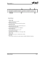
CHANNEL 1
LF gain control
This control sets the amount of cut or boost for the LF (Low Frequency) section. The
gain range in +15db and -15dB.
LF Q control
Varies the 'Q' (bandwidth) of the cut or boost region. A low Q, CW (clock wise) affects
a wide band of frequencies whilst a high Q, CCW affects a very small band.
LF Frequency control
This control selects the centre frequency for LF cut or boost. The LF frequency control
has a 40:1 range and is adjustable from 20Hz to 1kHz.
MF gain control
Sets the amount of cut or boost for the MF (Mid Frequency) section.
MF Q control
Varies the 'Q' of the cut or boost region for the MF section.
MF Frequency control
This control selects the centre frequency for MF cut or boost and is adjustable from
200Hz to 8kHz
HF gain control
Sets the amount of cut or boost for the HF (High Frequency) section.
HF Frequency control
This control selects the centre frequency for HF cut or boost and is adjustable from
500Hz to 20kHz.
HF Q control
Varies the 'Q' of the cut or boost region for the HF section.
CLIP LED
The Clip LED monitors the last stage of the EQ output stage. The LED lights 3dB
before clipping.
Bypass switch
Pressing BYPASS switches the EQ out of the signal path and allows A/B comparison.
Remember if you are using any amount of boost, bypassing the EQ will cause a
noticeable drop in signal level.
In MONO mode Channel 2 BYPASS is inoperative and Channel 1 BYPASS now
switches the whole EQ in and out of circuit.


