background image

VMAC 

– 

Vehicle Mounted Air Compressors


Toll Free:


1-888-241-2289 

Fax: 1-250-740-3201 

32 

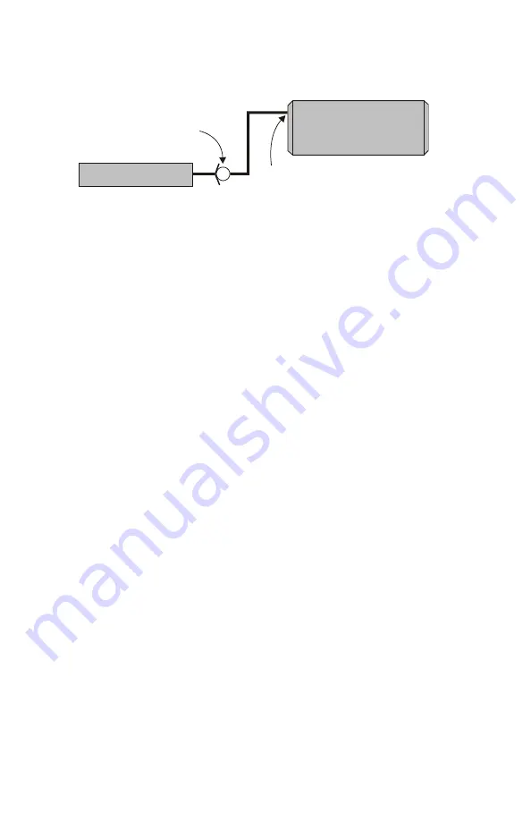
The line to the auxiliary tank must not be installed in the bottom of 
the tank, but must be installed as high as possible to prevent water 
from entering the line. 
 

Install the line as high as 
possible, NOT on the 
bottom of the auxiliary tank

VR Tank

One-way check valve

Auxiliary Tank


Figure 5.4 

Содержание V900104

Страница 1: ...2 2 Installing the Tank Assembly 7 Part 3 Installing the Cooler and Compressor 8 3 1 Installing the Oil Cooler 8 3 2 Installing the Main Bracket and Compressor 10 3 3 Connecting the Hoses 14 3 4 Compl...

Страница 2: ...bending or restructuring operations for correct fit in modified trucks must follow standard shop practices All hoses tubes and wires that are rerouted or shifted during installation must be secure so...

Страница 3: ...TANDARD GRADE 8 NATIONAL COARSE THREAD Size 1 4 5 16 3 8 7 16 1 2 9 16 5 8 Foot pounds ft lb 9 18 35 55 80 110 170 280 Newton meter N m 12 24 47 74 108 149 230 379 STANDARD GRADE 8 NATIONAL FINE THREA...

Страница 4: ...the air cleaner assembly and the passenger side intercooler tube Drain the coolant and remove the lower radiator hose save for use later Disconnect the fan clutch wire and remove it from the mounting...

Страница 5: ...side of the cylinder head Figure 1 2 and install the supplied 1 2 inch NPT nipple NPT elbow and NPT to 3 4 inch hose barb in the cylinder head port Face the elbow towards the passenger side of the tru...

Страница 6: ...on a workbench with the front oil filter end of the tank to your left and remove the oil filter Remove the two 1 4 inch pinch bolts from the C clamps Expand the clamps slightly and slide them over th...

Страница 7: ...and insert 5 16 inch bolts through the C clamps and the mount brackets install the nuts but do not tighten Check tank alignment then tighten the C clamp bolts Slide the tank all the way up on the tan...

Страница 8: ...he Oil Cooler Remove OEM hose clamps from OEM lower radiator hose Cut 2 sections out of hose as seen in Figure 3 1 Figure 3 1 Install cooler in engine bay on the passenger side beside engine Tab on co...

Страница 9: ...gh cooler with washer and nut on bottom side of the body lift tab Secure hoses with supplied hose clamps and tighten bolt to specifications Connect the supplied 3 4 inch heater hose to the fitting on...

Страница 10: ...cket in position on the engine so that you can see how it will mount once the compressor has been attached Figure 3 3 Angle the front of the bracket up during installation to hook the front stud over...

Страница 11: ...that the supplied 5 16 washer is installed on the hex head bolt that is closest to the front of the compressor and engine Apply Loctite and insert the rear M12 bolt through the bracket lift the compr...

Страница 12: ...5 Place the OEM crank pulley on the front of the crankshaft and rotate it to align it with the locating pin Route the belt as per Figure 3 6 but leave the belt loose Do not tension the OEM belt before...

Страница 13: ...belt routing diagram for the correct installation Figure 3 6 Tension the OEM belt Place the idler on the main bracket and install the fan shroud bracket so that it points toward the passenger side of...

Страница 14: ...member along the frame rail and connect it to the matching fitting on the back of the compressor Route the hose as far as possible from the engine cross member V900106 Only Connect the straight end of...

Страница 15: ...e matching fitting on the compressor and the fitting on the top of the cooler If needed loosen the locknut on the fitting and rotate it to attach the hose Tighten the locknut and make sure the hose cl...

Страница 16: ...spacer Figure 3 10 Make sure that there is sufficient clearance between the bracket and the OEM belt Use Loctite on the bolt Install the fan shroud nuts Install the fan clutch wire bracket using the...

Страница 17: ...d fasten it to the bracket to hold the hoses secure and away from the exhaust and suspension components Transmission bell housing Engine oil pan Bracket and hoses Front Figure 3 11 Remove the cab moun...

Страница 18: ...ake and the long end to the remote filter Tighten the inlet valve bolts and secure the hoses with the supplied clamps V900104 Only Insert the supplied spacers between the frame and the sway bar mount...

Страница 19: ...89 Fax 1 250 740 3201 19 Attach the intake guard plate using these three fasteners Flexible hose to remote air cleaner Sway bar spacer Compressor Figure 3 13 SUPPLIED BOLTS FRAME V900106 LARGE SWAY BA...

Страница 20: ...your warranty Remove the plug or open the outlet of the tank Remove the plug from the fill tube and slowly pour oil into the opening using a funnel Continue adding oil until the level is correct Insta...

Страница 21: ...k 3 pin connector To ground To ground Connect Blue Blue Blue Blue Connect to the park brake switch Connect to ECM connector 1 pin 37 dark blue wire with a gray stripe AUTOMATIC TRANSMISSION Connect lo...

Страница 22: ...Mount the throttle control under the dash to the right of the steering column so that the connectors will easily reach the accelerator pedal Secure it in place with ties Keep wires away from the park...

Страница 23: ...tic loom and route them from the firewall along the driver s side fender across the top of the radiator to the compressor Connect them to the matching connections at the compressor Connect the gray wi...

Страница 24: ...connector 4 2 1 6 7L Diesel Aisin AS68RC 35 45 5500 cab chassis Ram pick up Route the long blue wire from the throttle control to the transmission range sensor on the driver side of the transmission a...

Страница 25: ...long blue wire from the throttle control to the yellow wire with the dark blue stripe Figure 4 3 This wire should show 0 Volts in Park or Neutral and approximately 12 V in all other gear selections w...

Страница 26: ...ler Ground Blunt cut wires Figure 4 5 4 2 4 Ignitions switched 12V 2500 3500 pickup Locate the cigarette lighter power outlet at the instrument panel or power outlet console Solder and seal the red ig...

Страница 27: ...see if there is a number showing in the hour meter If there is no display there is no power to the control box Press the ON button The green light should come on and you should hear the compressor cl...

Страница 28: ...or body 5 2 After Starting the Engine Checklist Place the truck in a safe operating position and block the wheels Ensure that there are no people around the truck before beginning the test Make sure t...

Страница 29: ...as been operated Check the compressor oil level after the engine has been shut down and the oil level has had time to stabilize 5 3 Setup Performance Testing and Adjustments This system has been adjus...

Страница 30: ...lose the air valve slowly to allow the system pressure to rise 9 Once the system pressure is at maximum slowly open the ball valve on the test tool until the pressure on the gauge begins to drop Engin...

Страница 31: ...seen by truck operators Figure 5 3 Figure 5 3 5 5 Auxiliary Air Receiver If you intend to use an auxiliary air receiver with this system you must observe the following installation procedure to preve...

Страница 32: ...line to the auxiliary tank must not be installed in the bottom of the tank but must be installed as high as possible to prevent water from entering the line Install the line as high as possible NOT on...

Страница 33: ...Filter Regulator Lubricator Removes lubricants water and dirt from the air stream Adds atomized tool oil to lubricate tools Reduces pressure for longer tool life Hose Reel Secure compact retractable...

Страница 34: ...VMAC Vehicle Mounted Air Compressors Toll Free 1 888 241 2289 Fax 1 250 740 3201 34...

Отзывы: