VMAC - Vehicle Mounted Air Compressors
VMAC Technical Support: 888-241-2289
VMAC Knowledge Base: kb.vmacair.com
47
☐
Crimp the supplied fuse holder to the red wire running from the control module.
Ensure the fuse holder is installed as close to the power source as possible.
☐
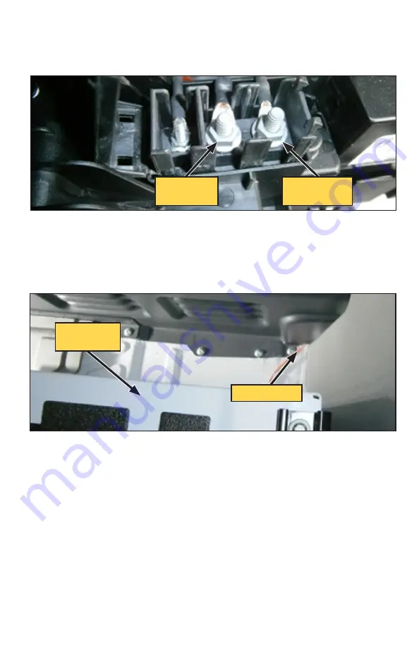
Connect the other end of the fuse holder to the terminal that holds the OEM
red wire with blue stripe (Figure 57).
☐
Connect the orange wire from the Control Module to the terminal that the OEM
black wire with brown stripe is attached to (Figure 57).
☐
Connect the green ground wire from the Control Module to a chassis ground.
☐
Route the WHASP fan and pressure switch harnesses from the Control Module
through the passthrough in the bulkhead to the cargo bay (Figure 58).
Figure 57 — Tying into vehicle power
Key switched
12 V
Constant
12 V supply
Figure 58 — Bulkhead passthrough
Passthrough
Driver seat
bracket
☐
If the interface panel will be mounted in the cargo bay, route its harness
through the bulkhead passthrough.
☐
Route the following wires from the Throttle Control and Control Module through
the grommet in the floor, beneath the driver seat, to the compressor (follow the
compressor hoses routed earlier)*:
☐
*White 16 AWG wire from the Control Module (clutch wire).
☐
*Grey cable with the green connector from the Control Module (Temperature
sensor).
☐
Connect the bullet connector on the white wire running from the Control
Module to the bullet connector on the black wire running from the compressor.
☐
Connect the green connector on the grey cable running from the Control
Module to the matching connector on the compressor.


