VITEK VT-DVR Series
117
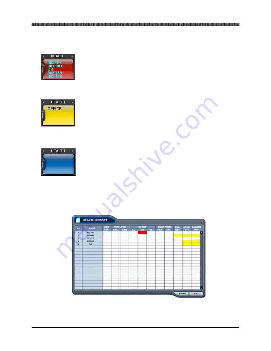
1) Warning
colors.
a. RED
The color changes to red when critical functions of the DVR is
interrupted or has failed: connection failure, connection timed
out, disconnection, power failure, fan lock/recovery, system
failure/recovery and HDD failure/recovery.
b. YELLOW
The color changes to yellow when recording and alarm related
events occur: video loss, video loss recovery, alarm trigger,
motion detection, recording stopped, schedule off and backup
stopped.
c. BLUE
The color remains blue as long as the DVRs are functioning
within the normal parameters. It will display the DVR’s set
name only with the following functions: recording started,
backup started and schedule on.
2) Health report
Health report can be accessed at any time by double-clicking on the warning led.
Health report allows a quick glance of all DVRs’ status. Maximum of 300 DVRs’
status can be displayed simultaneously.
Содержание VT-DVR
Страница 20: ...VITEK VT DVR Series 19 4 INSTALLATION AND CONNECTION ϖ Example of a normally open alarm circuit ...
Страница 30: ...VITEK VT DVR Series 29 Live view sequence of 16 CHANNEL DVR ...
Страница 79: ...VITEK VT DVR Series 78 The three ports are added as shown ...
Страница 94: ...VITEK VT DVR Series 93 2 DVR WEB CLIENT 1 2 3 4 5 6 7 8 9 10 11 12 13 16 15 17 14 18 ...
Страница 126: ...VITEK VT DVR Series 125 19 POWER Terminates and exits from the CMS ...
Страница 154: ...VITEK VT DVR Series 153 Notes ...


