


NTCS
April 2018
Visual Engineering
Video solutions. Integrated
visualengineering.co.uk
Page 23
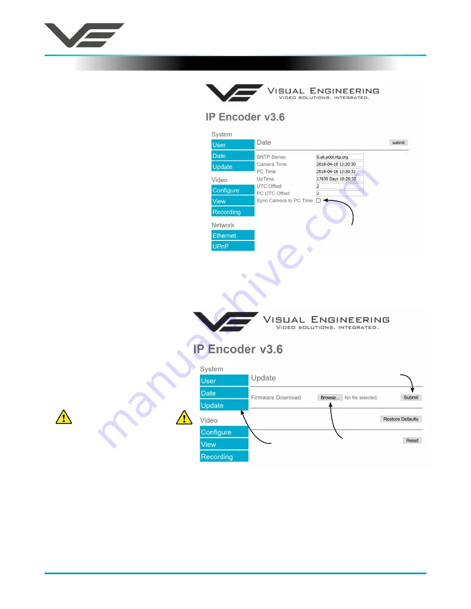
Date Menu
The date menu page allows the user
to synchronise the encoder time to
an SNTP server. In this instance it is
necessary to have the PC connected
to a network.
If a network connection is not
available it is possible to synchronise
the encoder to the PC time by ticking
the “Sync Camera to PC Time” check
box and pressing the
submit
button.
The “UTC Offset” can be altered to
align the camera time with the local
time zone. Changes are only enabled
when the
submit
button is pressed.
To align the camera to the actual PC
time the “UTC Offset” should be made
same as the value displayed in the “PC
UTC Offset” field.
Update Menu
Following a
Submit
the camera will update the firmware and display the following text:
Programming in Progress...Do NOT remove power
Wait until the web page clears this text before trying to move away from the current web page or
powering off the camera. Updates typically take approx 3 minutes to complete.
To fully ensure the upgrade has finished it is
strongly advised
to refresh the webpage and check
the banner displays the new firmware version number before switching off the power.
It is also
strongly advised
that following a firmware update that the
Restore Defaults
button is
pressed. This will revert the encoder back to a default start state.
It is possible to update the
firmware of the encoder. There
are three steps to updating the
firmware, as shown on the right.
3. Submit the file
Only update the encoder
with files that have
been approved by Visual
Engineering.
Use of other files will render
the encoder inoperable.
Tick this box and press
submit
to sync the camera to
the PC time
1. Select the
Update tab
2. Browse to the file


