background image

1 March, 2005 

V1682OPMA.doc 

Page 7 of 32


2.3.2 AES BNCs 

These are only available on the 16VR3P and 16VR1P rear panels.  They provide for unbalanced AES 
inputs and outputs for channels A and B.  With these rear panels it is not possible to have the second 
AES outputs or re-entrant audio. 


2.3.3 Audio I/O 

 
On the 16VR1L and 16VR3L rear panels there is a 44 way connector in the same footprint size as a 
standard 25 way D type connector.  It is used for all the audio connections, both digital and analogue, 
although many of them share pins, and other signals. Of course whether the audio signals are analogue 
or digital (or present at all) depends on the type of module fitted to the unit. 
 
If the HDD socket is to be used for audio and connected with multi-way cable it is essential that the 
audio pairs, both analogue and digital, are individually screened. 
 
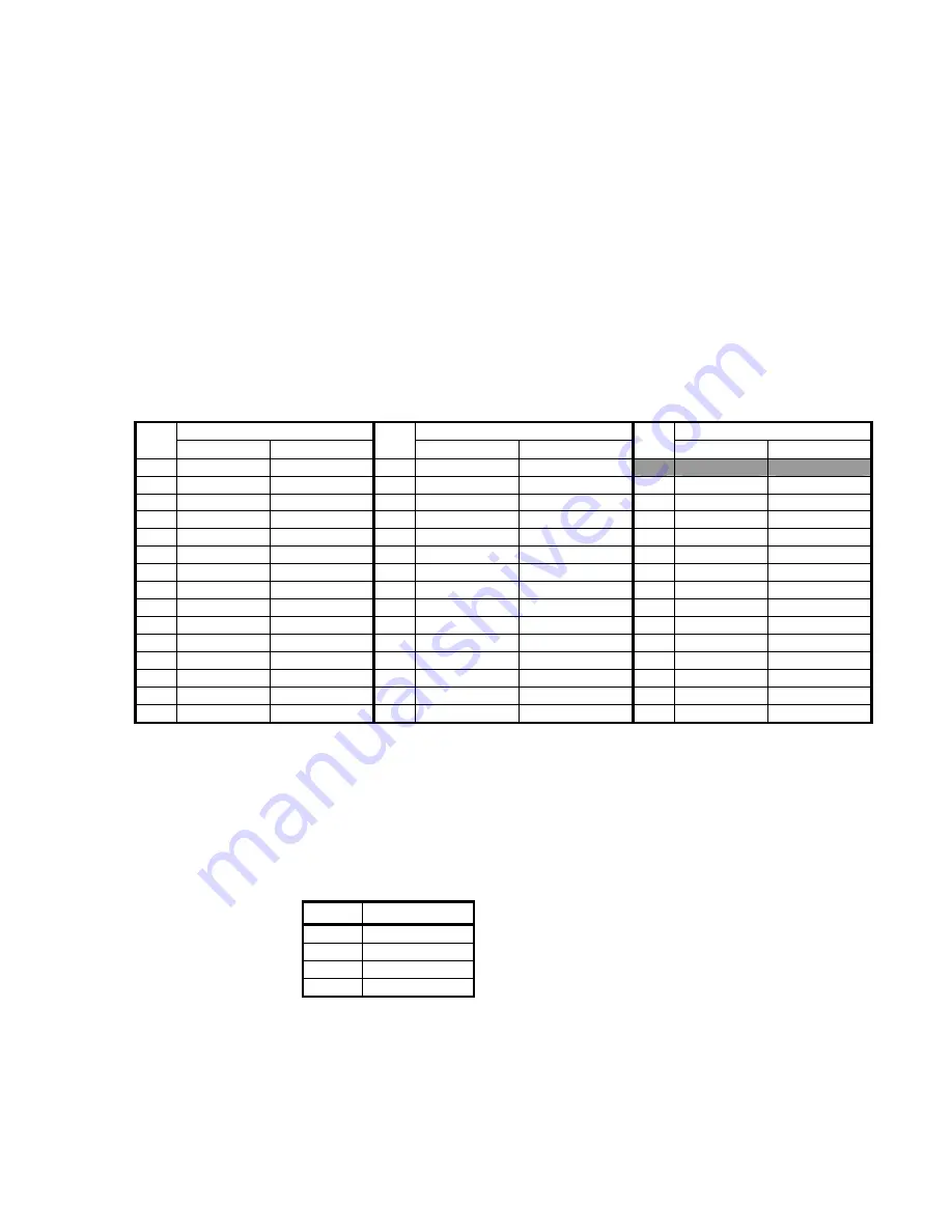
The signals to and from the pins on this connector are as shown in this table: 
 

Pin Signal Pin  Signal  Pin Signal 

 Analogue  Digital    Analogue 

Digital 

 Analogue  Digital 

15 GND 

GND 

30 GPI_3 

GPI_3 


14 ALinP 

AESAinP 

29 GND 

GND 

44 ALinN 

AESAinN 

13 ARinP 

AESAin75 

28 GND 

GND 

43 ARinN 

AESAin0 

12 BLinP 

AESBinP 

27 N/C 

N/C 

42 BLinN 

AESBinN 

11 BRinP 

AESBin75 

26 GND 

GND 

41 BRinN 

AESBin0 

10 GND 

GND 

25 GPI_2 

GPI_2 

40 GND 

GND 

9  ALoutP 

AESA1outP  24 GND 

GND 

39 ALoutN 

AESA1outN 

8  ARoutP 

AESA1out75  23 AESREFinP  AESREFinP 

38 ARoutN 

AESA1out0 

7  BLoutP 

AESB1outP  22 AESREFinN  AESREFinN 

37 BLoutN 

AESB1outN 

6  BRoutP 

AESB1out75  21 GND 

GND 

36 BRoutN 

AESB1out0 

5  GND 

GND 

20 GPI_1 

GPI_1 

35 GND 

GND 

4  AESCinP  AESA2outP  19 GND 

GND 

34 AESCinN  AESA2outN 

3  AESCin75  AESA2out75  18 AESREFin75 AESREFin75  33 AESCin0  AESA2out0 
2  AESDinP  AESB2outP  17 AESREFin0  AESREFin0 

32 AESDinN  AESB2outN 

1  AESDin75  AESB2out75  16 GND 

GND 

31 AESDin0  AESB2out0 


Notes:


1.  Pin 1 is at the bottom 


2.3.4 GPI  

 
The 16VR1P and 16VR3P panels have a separate Molex connector for external GPI connection.  (On 
the other panels the Audio I/O connector is used.)  The connections are: 
 

Pin Signal 

1 GND 
2 GPI 

3 GPI 

4 GPI 

 
The GPI inputs are currently unused on the V1682. 

Содержание V1682

Страница 1: ...82 VALID READER INSTALLATION and OPERATION Vistek Electronics Ltd Filename V1682OPMA doc Issue A Date February 2005 VISTEK Electronics Ltd Wessex Rd Bourne End Buckinghamshire SL8 5DT ENGLAND Tel 44 1...

Страница 2: ...13 3 1 6 Variable Calibration 13 4 Making measurements 15 4 1 Introduction 15 4 2 Video Input 15 4 3 Audio Input 16 4 4 MAL Maximum Analogue Level Setup 16 4 5 Reading Measurements From Front Panel 1...

Страница 3: ...Y 17 8 3 ANALOGUE AUDIO SUB MODULES 17 8 3 1 DAC 17 8 3 2 ADC 17 9 CONFIG MENU 17 10 FRONT PANEL MENUS 17 11 CONTROLs 17 11 1 VALID Measurements MEASURE 17 11 2 On Screen Display Controls VID OSD 17 1...

Страница 4: ...vided on the front panel indicating the audio video delay in milliseconds the originating channel and a warning if a channel is inverted The unit may take its audio input from an AES or analogue input...

Страница 5: ...connectors but not all signals are available This manual has generally been written assuming that one of the L type rear panels is being used with access to all signals 2 1 3 U REAR PANELS For the 3U...

Страница 6: ...ions but at the expense of losing some signals Connection details are given in section 2 3 2 3 CONNECTIONS 2 3 1 SDI BNCs On all the rear panel types the upper three BNCs are for SDI video as follows...

Страница 7: ...n Signal Pin Signal Pin Signal Analogue Digital Analogue Digital Analogue Digital 15 GND GND 30 GPI_3 GPI_3 14 ALinP AESAinP 29 GND GND 44 ALinN AESAinN 13 ARinP AESAin75 28 GND GND 43 ARinN AESAin0 1...

Страница 8: ...rate 32 48kHz Output Sample rate 48kHz AES Reference Balanced Zin 110 or HI Z Sample rate 48kHz AES Reference Unbalanced Zin 75 or HI Z Sample rate 48kHz ID SYNC 75 TTL 75R Positive pulse high during...

Страница 9: ...o reset the internal micro controller and DSP SKT 1 Audio Sub module Various sub modules are available for the different audio options See section 2 7 PL 3 JTAG Connector For development and test use...

Страница 10: ...the menu system may seem cumbersome but with only a small amount of practice it will become very easy to use 2 6 1 Direct Indications The four LEDs at the top of the panel provide these direct indica...

Страница 11: ...nd if not then the others show which direction to which it has been changed or that it is no longer on its CAL value 2 6 3 Remote Local Control The lowest switch selects between Local control and Remo...

Страница 12: ...Upper Case Sub Menu Menu items under each main heading such as Aud I P or Mux Grp under the AUDIO main menu These items are all in Sentence Case generally lower case but with upper case first letters...

Страница 13: ...e unit is set up to generate a VALID test signal However there is no direct indication as to the format the SDI input i e 625 50 or 525 60 Since many installations may use multiple formats and therefo...

Страница 14: ...e of making timing measurements even when the video from the V1681 has been reduced to any size down to screen with any additional stationary content in the picture as long as all but the VALID test s...

Страница 15: ...ing and source information is however also available for quick access at the top level of the menu tree 4 5 1 Quick Access For quick access to delay and source information press when at the top level...

Страница 16: ...elow Audio levels may be read under the MEASURE Aud Lev menu All level measurements are in dBu relative to 0 775mV RMS It should be noted that the level reading is always in dBu even if the input is d...

Страница 17: ...2 Figure 4 4 are shown the delay source display in various states Figure 4 2 shows the system operating correctly with audio and video synchronised and all four audio inputs fed by the correct V1681...

Страница 18: ...IEC 60268 10 Type IIb is provided on the right hand side of the on screen display The meter has a fixed range of 14 to 14 dBu with scale markings at 4 dBu intervals as shown Figure 4 5 The green to ye...

Страница 19: ...ain analogue or digital more importantly the levels are effected by the MAL Maximum Analogue Level setting if a digital input format is being used For more information on MAL see Sec 4 4 The V1681 gen...

Страница 20: ...ule AES analogue or through an embedded audio channel The audio input to the unit is set up in the AUDIO Aud I P menu which will have the following options dependent on the sub module fitted if any Mo...

Страница 21: ...either basic 20 bit form or in extended 24 bit form The embedding resolution can be controlled in the ENG ING Aud Bits menu in which the options are 20 or 24 bit All internal audio processing is done...

Страница 22: ...is no ability to blank only some lines Lines which are blanked Format VBI Lines 525 60 1 to 20 264 to 282 625 50 624 to 6 311 to 318 6 3 ANCILLARY BLANKING The ancillary data space may be blanked if n...

Страница 23: ...is information is also echoed in the STATUS Mod I Ps and Mod O Ps menus 7 3 INPUT STATUSES The status of all inputs other than analogue may be checked within the STATUS menu The SDI input can be monit...

Страница 24: ...on selected group DMX 20bt 20 bit audio being de muxed from selected group DMX 24bt 24 bit audio being de muxed from selected group 7 7 MULTIPLEXER STATUS The status of the audio multiplexer is avail...

Страница 25: ...1 March 2005 V1682OPMA doc Page 25 of 32 STATUS Videover 0 00 00 The Video FPGA data...

Страница 26: ...o sleep mode When the calibration mode is on then the unit will automatically set up the required conditions in the unit as you enter each sub menu For example if you go into the CntrFreq sub menu the...

Страница 27: ...AC By turning Calibrate Mode ON and selecting one of the DAC sub menus the unit will automatically generate tone with an MAL of 18dBFS To calibrate the frequency set the unit to generate Tone by turni...

Страница 28: ...contains has no user adjustable controls The only function of this menu is to set the unit into a diagnostic test mode In order for the unit to be put into test mode a password is required This shoul...

Страница 29: ...L stat BR stat MEASURE VID OSD AUDIO STATUS ENG ING CALIB CONFIG Aud A VALIDMtr Aud I P Sub Mod VBI Cal Mode Password Aud B SDI Src Mux Grp Mod I Ps Anc Data CntrFreq TestMode Aud Lev Mute Mod O Ps Au...

Страница 30: ...delayed 40ms with respect to vid AR 0023 Channel A right is leading video by 23 ms AR AL Aud A AL AR AL input inverted Left Right swap over on channel A BL 0000 BR 0000 Lip synch correct AL BL MEASURE...

Страница 31: ...is occupied 3 SDI input has Group 3 only is occupied 4 SDI input has Group 4 only is occupied I P Grps 2 4 Group 2 and 4 for example occupied No DMX DMX 20bt DMX Aud DMX 24bt MUX OK Mux Grp MUX over G...

Страница 32: ...28 0 n DAC A R 127 128 0 n DAC B L 127 128 0 n 127 DAC B R 128 0 n ADC A L 127 128 0 n ADC A R 127 128 0 n ADC B L 127 128 0 n CALIB ADC B R 127 11 7 CONFIGURATION CONFIG On n Banner Off Password 0 Of...

Отзывы: