


VISTEK V1679 single-mode fibre
data transceiver
22
Issue 1
5.2
Electrical Interfaces
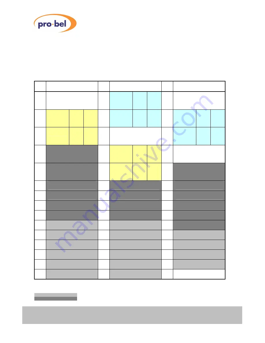
All General Purpose Interface (GPI) signals and the Serial Comms Port signals are available on a 44-pin,
high density D-type connector. The following table shows the Connector Pinout:
Note that GPIO pin pairs (GPIO_Px, GPIO_Nx, x = 1..16) are either used as inputs or outputs. The naming
convention is with reference to the opto-isolated inputs, where the '
P
' (positive) pin drives the LED's Anode
and the '
N
' (negative) pin is either grounded internally or it drives the LED's Cathode.
Pin
Signal
Pin
Signal
Pin
Signal
1
+15V (fused, 1A max.)
16
COM2_Rx2
RS232
RxD
RS422
Rx+
31
GND
2
COM1_Rx2
RS232
RxD
RS422
Rx+
17
COM2_Rx1
RS232
CTS
RS422
Rx-
32
COM2_Tx2
RS232
RTS
RS422
Tx+
3
COM1_Rx1
RS232
CTS
RS422
Rx-
18
GND
33
COM2_Tx1
RS232
TxD
RS422
Tx-
4
GPIO_N16
Group B
19
COM1_Tx2
RS232
RTS
RS422
Tx+
34
GND
5
GPIO_P16
Group B
20
COM1_Tx1
RS232
TxD
RS422
Tx-
35
GPIO_N15
Group B
6
GPIO_P14
Group B
21
GPIO_N14
Group B
36
GPIO_P15
Group B
7
GPIO_P13
Group B
22
GPIO_N13
Group B
37
GPIO_N12
Group B
8
GPIO_P11
Group B
23
GPIO_N11
Group B
38
GPIO_P12
Group B
9
GPIO_P10
Group B
24
GPIO_N10
Group B
39
GPIO_N9
Group B
10
GPIO_P8
Group A
25
GPIO_N8
Group A
40
GPIO_P9
Group B
11
GPIO_P7
Group A
26
GPIO_N7
Group A
41
GPIO_N6
Group A
12
GPIO_P5
Group A
27
GPIO_N5
Group A
42
GPIO_P6
Group A
13
GPIO_P4
Group A
28
GPIO_N4
Group A
43
GPIO_N3
Group A
14
GPIO_P2
Group A
29
GPIO_N2
Group A
44
GPIO_P3
Group A
15
GPIO_P1
Group A
30
GPIO_N1
Group A
Screwlocks:
GND
Table 1 : 44-Pin High Density Dsub Connector Pinout
Legend:
Signals belonging to Group A
Signals belonging to Group B