25
Installation
I
NSTALLATION
I
NTO
F
ACTORY
B
UILT
F
IREPLACES
:
When installing the fireplace insert into a zero clearance fireplace,
DO NOT
cut or modify any factory
firebox parts. If the fireplace insert does not fit into a zero clearance fireplace, we recommend you use
a freestanding model and install as a hearth mounted unit.
Install a 3” (76 mm) flex pipe from the stove
to the top of the chimney (see “
H
EARTH
M
OUNT
I
NSTALLATION
- F
REESTANDING
:
”).
1. This insert must be tested and meet requirements of UL 1482 ULC S629 when tested in a masonry
fireplace built per ULC S628
2. The factory built fireplace must be listed per UL 127 or ULC S610
3. Installation must include a full height listed chimney liner meeting type HT requirements. This liner
must be securely attached to the insert flue collar and the chimney top.
4. Means must be provided to prevent room air passage to the chimney cavity of the fireplace. This may
be accomplished by sealing the damper area around the chimney liner or sealing the fireplace front.
5. The air flow within and around the fireplace shall not be altered by the installation of the insert
(no louvers or cooling air or outlet ports blocked) unless specifically tested as such for each factory
built fireplace manufacture and model line. (NOTE: using a louver faceplate complies with the
requirement).
6. Alteration of the fireplace in any manner is not permitted with the following exceptions: external trim
pieces which do not effect the operation of the fireplace may be removed providing they can be stored
on or with the fireplace for re assembly if the insert is removed. The chimney damper may be removed
to install the chimney liner.
7. Circulating chambers may not be blocked.
8. Means must be provided for removal of the insert to clean the chimney flue.
9. Insert that projects in front of the fireplace must be supplied with appropriate supporting means
A permanent metal warning label must be attached to the back of the fireplace stating that
the fireplace must be restored to its original condition for safe use with out the insert.
I
NSTALLATION
OF
C
ONTROL
P
ANEL
INTO
S
URROUND
P
ANEL
- I
NSERT
:
����
Figure 31: Control
Panel Cover.
Figure 32: Control
Panel Back.
When installing the control panel into the surround panel,
the surround does not need to be assembled. The control
board will be found in behind the firebox.
Place the control panel on the backside of the right
surround panel so the hinge is on the outside and the top
and bottom holes on the control panel line up with those on
the surround. Attach using two (2) T-20 screws through the
front of the surround into the circuit board control panel.
After the surround has been assembled and is ready to be
installed on the unit, plug the wiring harness into the control
panel (see Figure 32).
Содержание VF 100A
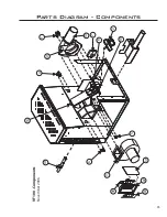
Страница 35: ...35 Parts Diagram Components...
Страница 36: ...Parts Diagram Steel 36...

