


Barcode reader VB34
Installation
Da
te
of
issue
06/
1
3
/2005
43
Subject to reasonable modifications due to technical advances.
Copyright Fuchs, Printed in Germany
Fuchs Group • Tel.: G49 621 776-0 • USA +1 330 4253555 • Sin65 67799091 • Internet http://www.pepperl-fuchs.com
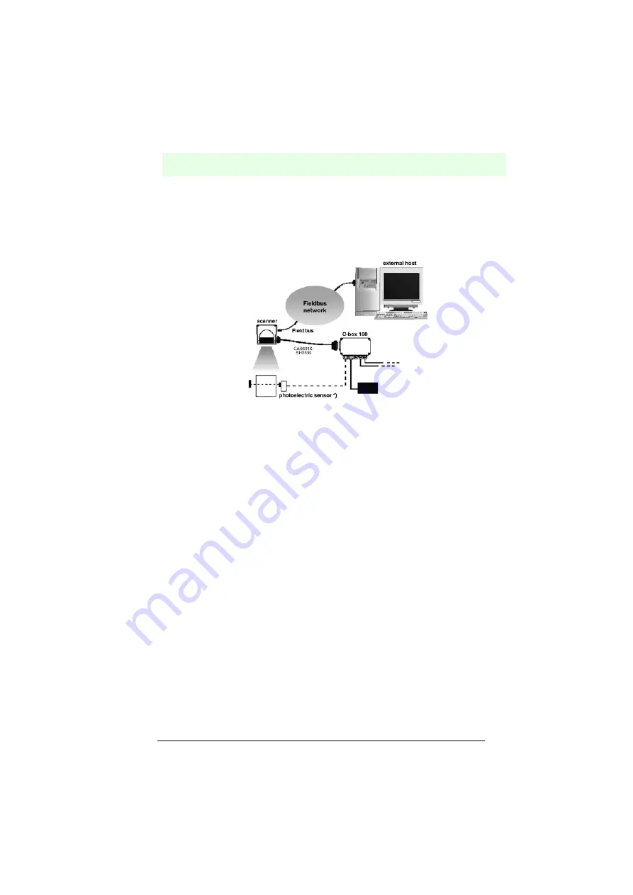
Fieldbus models
In this case, no external trigger is used. The C-BOX 100 is used only to supply the
reader. The VB34 reader (as an Ethernet, DeviceNet or Profibus model) is connected
to an external fieldbus host. It can be activated by a signal from the external host or
always be active in automatic operation mode.
*) Light barrier (presence sensor) connected to the external trigger input .
Figure 6.47
Point-to-point arrangement for fieldbus models
6.7.2
Loops
With the loop arrangement via the secondary interface, all VB34 models can be
integrated into a network with different readers, without the need for a Lonworks
interface.
In this loop arrangement, two or more readers can be connected to a single external
serial interface. Each VB34 reader also provides the messages, which it received on
the secondary (RS232) interface, via the primary interface (also RS232).
In this arrangement, several readers can be switched in series. The message passes
through all the stations in the chain up to the host. The read cycles of the individual
readers are independent of those of the other readers. In loop configurations, each
reader has an own external trigger (several light barriers).
For this purpose, a portable reader can also be included via the secondary serial
interface in order to read codes manually.
The maximum cable length for RS232 connections is 15 m.
The following figure shows several VB34 readers in a loop arrangement.


