


Barcode reader VB34
Installation
Da
te
of
issue
06/
1
3
/2005
23
Subject to reasonable modifications due to technical advances.
Copyright Fuchs, Printed in Germany
Fuchs Group • Tel.: G49 621 776-0 • USA +1 330 4253555 • Sin65 67799091 • Internet http://www.pepperl-fuchs.com
6.3.1
Primary/secondary interface and I/O connections
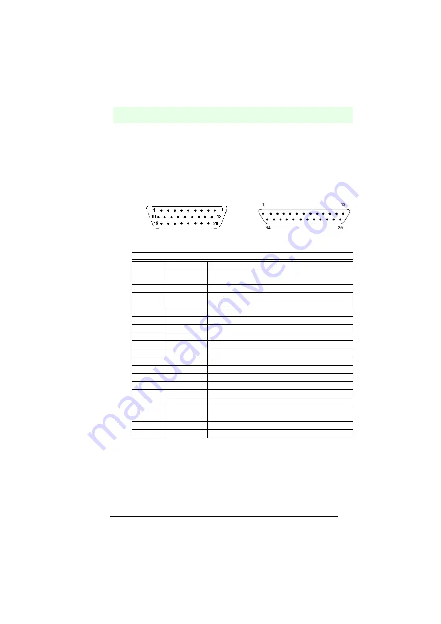
The VB34 reader has a 25-pin Sub-D connector for connection to computer, voltage
supply and input/output signals.
The fieldbus models (Ethernet, DeviceNet and Profibus) of the VB34 are equipped
with a 26-pin connector instead of the 25-pin connector.
The connection layout of this connector is shown in the following table:
Figure 6.11
26-pin connector 25-pin connector
*
Pin 26 is only present on fieldbus models (Ethernet, DeviceNet or Profibus).
VB34 connection layout of the 25/26-pin Sub-D connector
Pin
Description
Function
1
Shield
The shielding is internally connected with chassis
ground via a capacitor.
20
RXAUX
Received data of the RS232 interface (ground-related)
21
TXAUX
Transmitted data of the RS232 interface (ground-
related)
8
Out 1+
Plus lead of the digital output 1
22
Out 1-
Minus lead of the digital output 1
11
Out 2+
Plus lead of the digital output 2
12
Out 2-
Minus lead of the digital output 2
16
Out 3A
Digital output 3 - polarity exchangeable
17
Out 3B
Digital output 3 - polarity exchangeable
18
EXT_TRIG A
External trigger (polarity exchangeable)
19
EXT_TRIG B
External trigger (polarity exchangeable)
6
IN 2A
Input signal 2 (polarity exchangeable)
10
IN 2B
Input signal 2 (polarity exchangeable)
14
IN 3A
Input signal 3 (polarity exchangeable)
15
IN 4A
Input signal 4 (polarity exchangeable)
24
IN_REF
Common reference earth for IN3 and IN4 (polarity
exchangeable)
9, 13
VS
Supply voltage - plus
23, 25, 26* GND
Supply voltage - minus (ground)


