Document: CL140072
L2174 Manual Issue 2.0
Page 16 of 26
9
M
AIN
D
ISPLAY
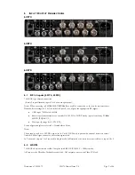
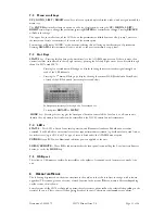
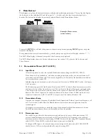
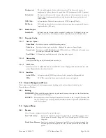
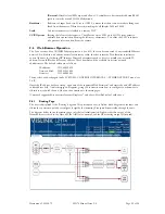
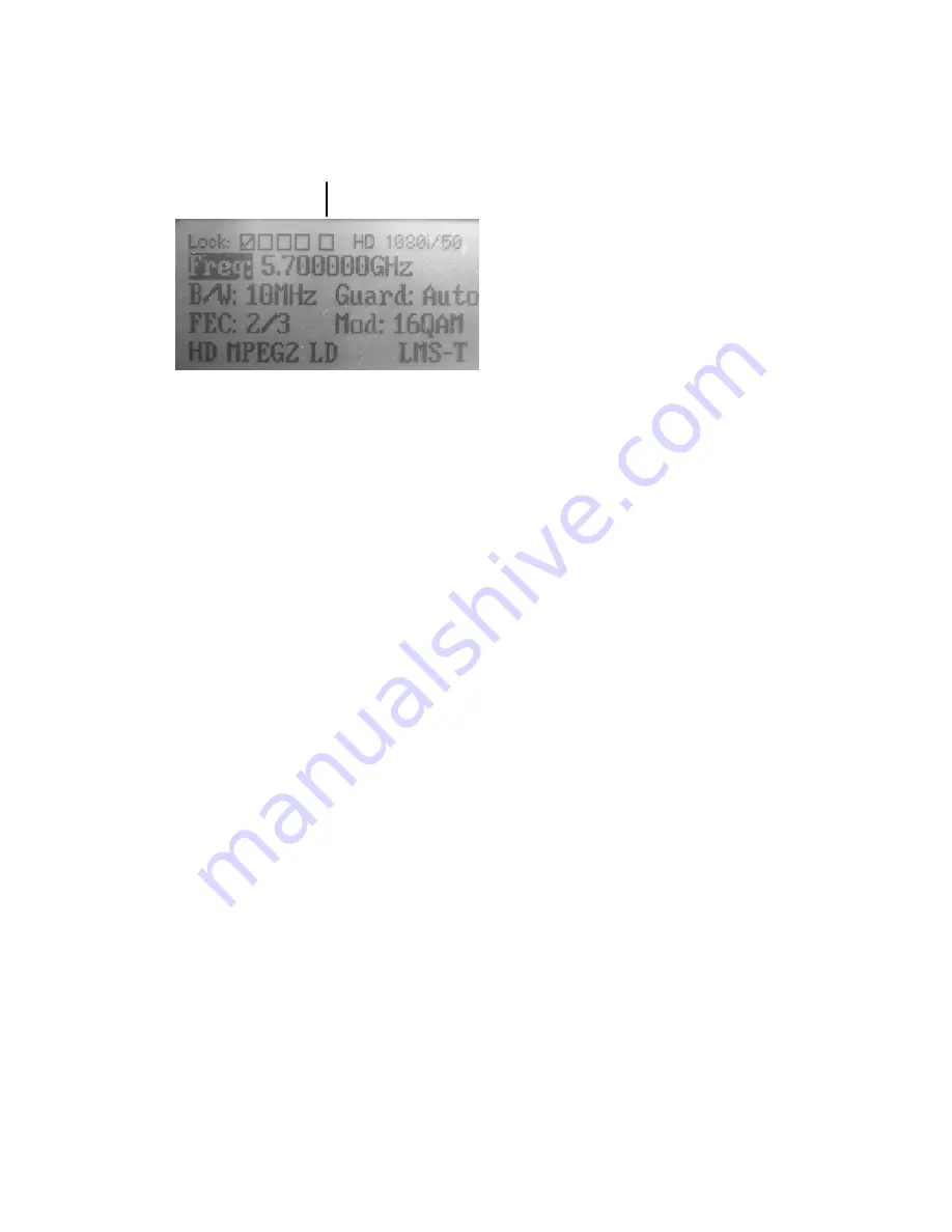
This displays, at a glance, the current frequency selection and modulation parameters. The top line also displays
the lock status of the individual RF and ASI inputs (
9
= locked ), and the video format detected by the
decoder. The bottom line displays the currently selected Decoder and Demodulator Modes.
RF Lock
Status 1-4
ASI Lock
Decoded
Video Format
Decoder mode
Demodulator mode
Pressing the
MENU
key will take the operator to the main setup menus; pressing
MENU
again at any point
returns to this display.
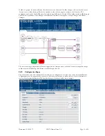
If any parameter has not yet been initialised (e.g. shortly after power-up), then it will display as dashes (“---“).
The L2074 Main display is identical, except the Video Format is not displayed.
The L2170 Main display shows the Service selection menu (see section 9.2.1), plus the ASI lock status and
Video Format.
9.1
Demodulator Menus (L2174, L2074)
9.1.1
Input Mode
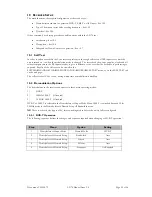
Allows the operator to select the required Modulation scheme being used (DVB-T, LMS-T).
When the unit is first switched on, and when switching modulation modes, the unit performs a self
test routine on the RF front end. This causes a slight delay (15-30s) before the demodulator will lock.
For more details see section 10.2
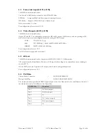
Individual inputs can be turned on and off as required. Note that in 20MHz LMS-T mode, only Inputs
1 & 2 are active.
The Receiver supports the Link Remote Triax System (L1273/4), which allows downconverters to be
sited remotely (up to 1km from the receiver). This can be set to Single or Dual mode; in Single mode,
2 downconverters are mounted remotely, and the triax system is connected to RF1 and RF2 on the
Receiver. The other 2 inputs can be connected directly to downconverters. In Dual mode, two triax
systems are connected, to RF 1/2 and RF3/4 respectively. This feature defaults to Off.
9.1.2
Demodulator Setup
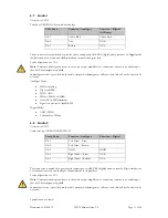
Operator can configure Frequency, Bandwidth, Guard Interval and Polarity. Apart from Frequency, all
have ‘Auto’ modes, which allows the Demodulator to detect the correct configuration from the
received signal.
If a frequency is entered that is outside the range of the currently selected downconverter, then an
‘Invalid Frequency’ alarm will occur, and reception will not be possible,
9.1.3
Downconverters
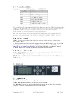
For each RF input, select the downconverter type, and turn on power to the downconverter. All
current Vislink downconverters are listed, or the Local Oscillator (LO) frequency of any unlisted
downconverter may be entered by selecting OTHER. To enter the incoming UHF frequency directly,
select NONE. When NONE is selected, downconverter power is disabled.
To change all RF inputs to the same downconverter settings at the same time, SET ALL INPUTS
should be set to ON; to set them individually, turn this setting OFF.
Example Home screen
(when locked)

