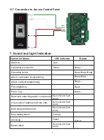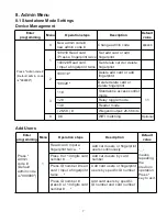
background image

5. Wiring

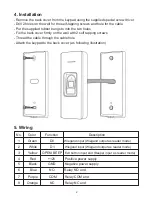
4. Installation

No.       Color          Function                                 Description

1         Green              D0           Wiegand input (Wiegand output as reader mode)
2          White              D1           Wiegand input (Wiegand output as reader mode)
3         Yellow     OPEN/ BEEP   Exit button input end (Beeper input as reader mode)
4           Red             +12V          Positive power supply
5          Black            GND          Negative power supply
6           Blue              NO           Relay NO end
7         Purple            COM         Relay COM end
8        Orange             NC           Relay NC end

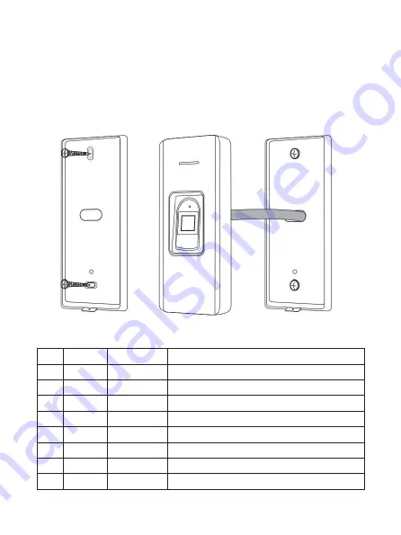
- Remove the back cover from the keypad using the supplied special screw driver
- Drill 2 holes on the wall for the self-tapping screws and hole for the cable
- Put the supplied rubber bungs to into the two holes
- Fix the back cover firmly on the wall with 2 self tapping screws
- Thread the cable through the cable hole
- Attach the keypad to the back cover. (as following illustration)

2

Содержание VIS-3024

Страница 1: ...Fingerprint Reader for Access Control for Single Door User Manual VIS 3024 www visionistech com...

Страница 2: ...Contain reader mode the transmission format could be adjusted by user Support multi access ways Card Fingerprint multi cards or multi fingerprint Support admin add card admin add fingerprint admin del...

Страница 3: ...D Negative power supply 6 Blue NO Relay NO end 7 Purple COM Relay COM end 8 Orange NC Relay NC end Remove the back cover from the keypad using the supplied special screw driver Drill 2 holes on the wa...

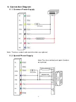
Страница 4: ...6 Connection Diagram 3 6 1 Common Power Supply Note The door contact and alarm function are optional Note The door contact and alarm function are optional 6 2 Special Power Supply...

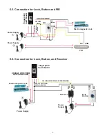
Страница 5: ...6 4 Connection for Lock and Button Power Supply Electromagnetic Lock Exit Button COM NO COM PURPLE WIRE NC ORANGE WIRE OPEN YELLOW WIRE FROM KEYPAD READER FROM KEYPAD READER FROM KEYPAD READER Finger...

Страница 6: ...it Button Power Supply COM NO NC PIR COM YELLOW WIRE ORANGE WIRE PURPLE WIRE FROM KEYPAD READER Power Supply Electromagnetic Lock Exit Button Power Supply COM COM NO NO NC YELLOW WIRE FROM KEYPAD READ...

Страница 7: ...t programming Press digital key Press key Read card under fingerprint code mode On process of reading multi user card Enter programming mode Enter setting status Unlocking Buzzer alarm Beep Beep Beep...

Страница 8: ...rint 11 Standalone access control mode 12 Relay toggle mode 13 Reader mode 26 58 Wiegand output 26 58 bits 8 WIFI matching Optional 8 3 2 1 0 11 Enter programming Menu Operation steps Description Defa...

Страница 9: ...elete card users by reading card Delete fingerprint users by inputting fingerprint means repeating the previous operation Press key to exit Press Admin code Default admin code is 999999 0 Advanced Set...

Страница 10: ...card Input a fingerprint twice 10002 Read card Input a fingerprint twice 10001 Set admin add card or admin add fingerprint Set admin delete card or admin delete fingerprint Delete admin add card or a...

Страница 11: ...e first time you will hear short BEEP sounds twice and the indicator light turns orange it means you have entered into delete user programming when you read the admin delete card admin delete fingerpr...

Отзывы: