


VC_nano_Series.pdf – VC nano Series Smart Cameras Operating manual
1996-2014 Vision Components GmbH Ettlingen, Germany
19
In case of unstable power supply (voltage spikes or power interruptions) it is recommended to backup
the power supply by a capacitor or a battery large enough to prevent power interruptions.
It is recommended to switch on the low voltage supply (12 to 24V) when booting the camera. Some
110/ 220V power supplies increase the output voltage too slow or drop the voltage under load at start
– up which might cause the camera not to boot properly! A power supply able to supply a much higher
than nominal boot current for a few milliseconds may be an alternative approach.
3.2.3
Electrical Specifications digital PLC IO / trigger Interface
The VC nano Series Smart Cameras feature digital inputs and outputs that allow e.g. direct input of
light barriers signals or the control of pneumatic valves, as well as a trigger input and output.
Please observe the current and voltage ratings specified in the following sections.
The PLC circuit of all VC Professional and Optimum Smart Cameras is separated from the camera
power supply. This however is not the case with models VC4016/4018/4002L and VC nano Series.
The different interface features for these camera ranges are shown in the following table.
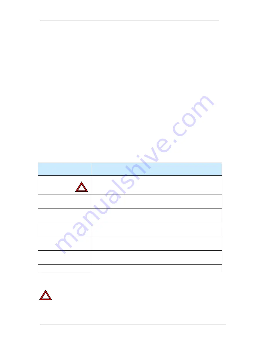
VC nano Series
(same as VC4016/4018/4002L)
Separation of
PLC/trigger output
voltage
PLC outputs supply
not
separated from power supply
PLC/trigger Input
Voltage
Identical with power supply voltage
PLC/trigger Input
Current (max)
1.0 mA at 12V to 2.0mA @ 24V
PLC/trigger Output
Voltage
Identical with power supply Voltage – internally connected
PLC/trigger Output
Current (max)
4 x 400 mA
Max total of all outputs: 1A
Max Current for 1 Power
/ PLC connector pin
500 mA
Power failure detection
-
When using the PLC/trigger outputs connect all camera supply and PLC supply pins (pin 1, pin
2 and pin 9) in order to limit the connector pin current.
The maximum combined current of all outputs should not exceed 1 A.
!
!