8) VOLUME CONTROL
Adjust the volume control for the desired sound level. Turn clockwise to
increase and counter clockwise to decrease.
9) MONITOR POWER CONNECTOR
Insert the supplied power cable connector fi rmly until it is locked. To remove
the power connector, press in the clip and pull out the connector, while
holding the clip down.
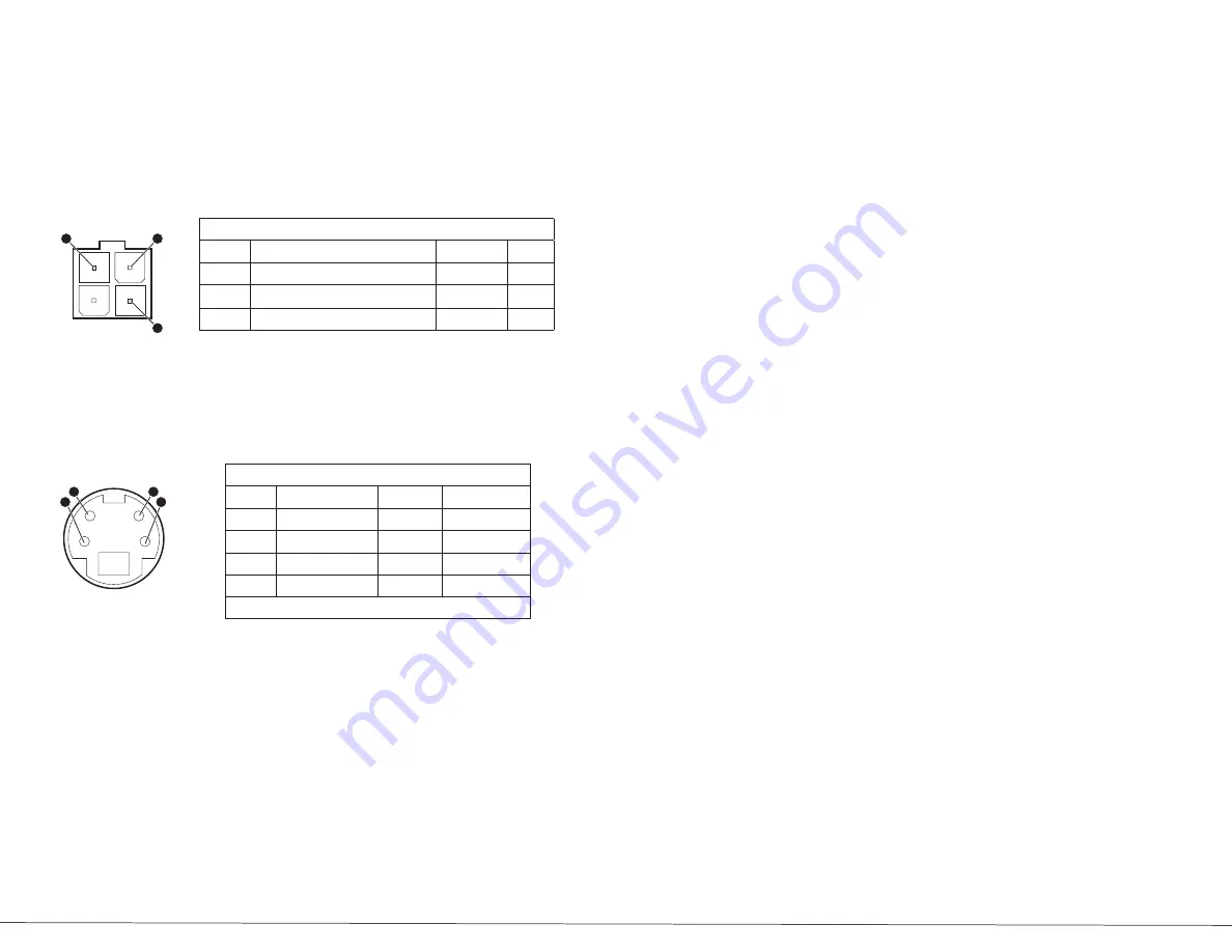
10) CAMERA INPUT CONNECTOR
There are two mini DIN type connectors for the video camera inputs. Connect
the black and white video cameras to the monitor with the supplied cable.
The monitor supplies power to the camera.
11) VCR JACKS
12) NORMAL/MIRROR OPTION
When the switch is in
MIRROR
position, the picture will be reversed. When the
switch is in
NORMAL
position, the picture will be normally displayed.
Camera 1
and
Camera 2
are operated individually.
7
6
Tools Required for Troubleshooting
DVOM (Digital Voltmeter)
•
Phillips screw driver #1 and #2
•
3/32” allen wrench
•
Oscilloscope
•
Tone generator
•
Terminal tool kit
•
(such as Snap-On Tt600 if swapping Clarion
components for Safety Vision)
Operating and Troubleshooting Instructions
When you turn the ignition key to the
accessory
or
on
position, power is supplied
to the monitor. The system will turn on automatically when the vehicle is
shifted into reverse. Pushing the
Power Button
, will also manually activate the
system, which allows the operator to use the system while driving. The green
LED on the monitor will illuminate at that time.
Note the power of the monitor:
When you push the power switch to the S/B position, the monitor is placed
in a S/B mode. The monitor is not turned off until the ignition key is in the off
position.
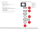
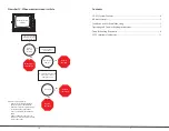
See the following three pages for these conditions:
Monitor has power but no picture
•
(see Flowchart A)
Monitor screen is black
•
(see Flowchart B)
Monitor screen is white
•
(see Flowchart C)
1
2
3
1
3
2
4
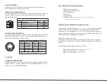
Monitor’s Power connector pin description
Pin No. Description
Value
Tool
3
Red: positive power
10 - 26 VDC
DVOM
2
Green: R
(reverse)
gear power
(optional)
10 - 26 VDC
CVOM
1
Black: ground
Camera input connector pin description
Pin No.
Description
Value
Tool
1
Power Supply
12 VDC
DVOM
2
Audio Input
35 decibel
Tone generator
3
Image Reverse
4
Video Input
1.0V p-p
Oscilloscope
Outer shield of connector housing is ground


