background image

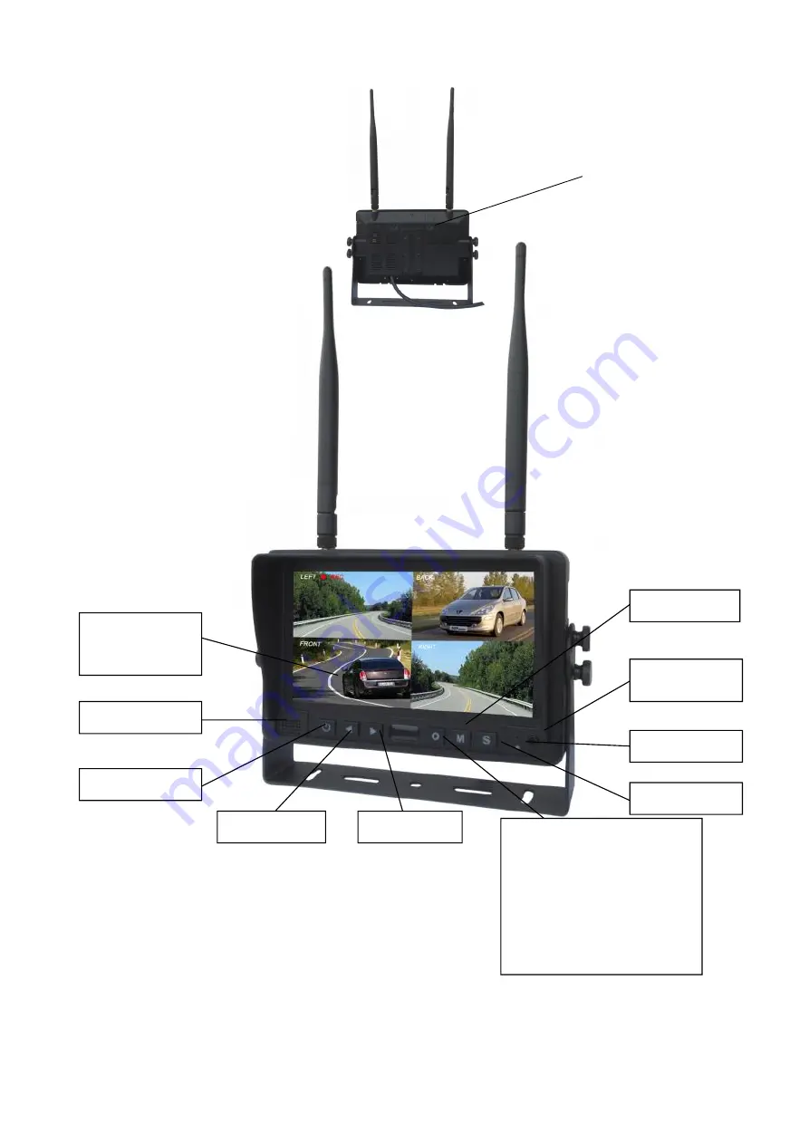
5. Parts Identification

Power switch

Volume increase

Press O button to enter

menu item or save user

settings.

Press O button - shortcut

for start/stop recording.

Press O button for 3

seconds - shortcut for

PAIRING.

Menu

Digital Color
LCD screen

Remote control

sensor

Light level

Volume decrease

Select channels

Loudspeaker

Micro-SD Slot

Содержание VWIC7WR

Страница 1: ...erchandise that is not returned within 30 days of the invoice date is subject to a restocking fee of 15 Contact your Vision Works dealer for return information Merchandise that has been special ordered cannot be returned for credit Non stock items returned for credit will be subject to vendor s return policy Important 1 To prevent short circuit make sure that the system is not plugged in or receiv...

Страница 2: ...Monitor Quantity 1 Camera with Magnet Quantity 1 Main Harness Quantity 1 Cigarette Lighter Adapter Quantity 1 Power Lead Quantity 1 Adhesive Monitor Base Quantity 1 ...

Страница 3: ... the camera as a preventative measure in the event the camera is knocked off 1 Slotted holes of the universal base mount can be used to position and permanently attach the monitor base to structure 2 Installer must ensure that attaching hardware is suitable to support the weight of monitor and base 3 Once the base has been fastened into position the monitor can be installed Adjust monitor to desir...

Страница 4: ...s put into reverse If this is your preference please attach this wire to the appropriate connection on your vehicle Ref Fig 2 BLACK and RED Wire of MAIN HARNESS Place camera in desired blind spot near a power supply First connect your power lead to your camera Please place protective tape over this connection to ensure no water damage Connect BLACK wire of Power Lead to ground Connect RED wire of ...

Страница 5: ... left of your screen reads Cam 1 If it reads Cam 1 Scan please click the S button two more times 3 Click M button to go to menu If you do nothing for 10 seconds the menu will go away 4 Hit left button 1 time to highlight pairing and press O to make the selection ...

Страница 6: ...amera Use a paper clip to click the pairing button on the back of the camera as shown below 6 If you click the pairing button on the camera after your camera has been paired you will lose signal and have to re pair your camera to your monitor ...

Страница 7: ...Operating Instructions 2 4G Digital 7 Wireless Color LCD Monitor Please read this manual thoroughly before operating the device and keep it for future reference V 1 3 ...

Страница 8: ...itor is not designed to be waterproof Operating Precautions 1 The device may be powered by a 12 or 24 volt automotive battery or vehicle electrical system 2 Make sure all cables are connected properly Observe polarity Improper cable connections may damage the monitor Remove the power cable connections when you do not intend to use the device Warning 1 High voltage is present within the monitor The...

Страница 9: ...Auto switch to the working channel when trigger is activated 3 Technical Specifications LCD size 7 Resolution 800 x 3 RGB x 480 Contrast 500 1 Brightness 400 cd m Viewing Angle U 50 D 70 R L 70 Dot pitch 0 0642 W x 0 1790 H Aspect Ratio 16 9 Channel 4 channels Operating Frequency 2400 2483 5 MHz Receiving Sensitivity 89 dBm Decompression Form MPEG4 Transmit Output Power 17 dBm Modulation 2 4G FSK ...

Страница 10: ...ton to enter menu item or save user settings Press O button shortcut for start stop recording Press O button for 3 seconds shortcut for PAIRING Menu Digital Color LCD screen Remote control sensor Light level Volume decrease Select channels Loudspeaker Micro SD Slot ...

Страница 11: ...nter mounting bracket 7 2 Installation of U support Bracket Support attaching piece Knob Single red wire to positive power supply of DC 10 32V Single black wire to GND Single brown wire to positive power wire of back up light Single white wire to positive power wire of left light Single blue wire to positive power wire of right light Single green or yellow wire to any other trigger control ...

Страница 12: ...e right turn indicator is activated 7 3 4 When the brown wire is connected to the positive wire of back up light the monitor automatically switches to CAM4 back up camera when the back up light is turned on The distancing grid will also be displayed 7 3 5 When the yellow wire is connected to the positive wire the monitor automatically switches to quad or split display Connection depends on the app...

Страница 13: ...play the following options and settings 1 MODE 2 PICTURE 3 MIR FLIP 4 RECORD 5 AUTOSCAN 6 SYSTEM 7 PLAY 8 PAIRING 1 Press or to select MODE Press to enter the submenu and press or to select QUAD H SPLIT SPLIT Press return to main menu 2 Press or to select PICTURE and press to enter the submenu ...

Страница 14: ...en the icons turn red press or on menu for selection decreasing or adding Press to exit the menu At the submenu press return to main menu 3 Press or to select MIR FLIP and press to select Press or to select NORMAL MIRROR MIR FLIP FLIP Press return to main menu 4 Press or to select RECORD Press to enter ...

Страница 15: ...n menu REWRITE When disk is full the monitor will delete the earliest manual timing record file one by one and keep recording FORMAT Micro SD card must be formatted before being used All documents in TF card will be lost once users format the disk 5 Press or to select AUTOSCAN Press to enter Press or to select CAM1 CAM2 CAM3 CAM4 SCANTIME and then press to enter the setting accordingly When the ic...

Страница 16: ...finishing the previous operation COLOR SYS Press or to select COLOR SYS Press to enter Press or to select NTSC PAL AUTO DIM Press or to select AUTO DIM Press to enter and then press or to select ON OFF When it is on the monitor will automatically turn darker when it is placed in dark environment for 5s ELETRONIC DISTANCE LABEL Press or to select ELETRONIC DISTANCE LABEL Press to enter and press or...

Страница 17: ...ile folder includes the video files which are named in format of HHMMSS_Channel Source 1 2 3 4 For example 130903 stands for year 2013 September 3rd 100953_3 stands for 10 09 53 am Cam3 The recording file format is AVI maximum recording time for every single file will last for 10 minutes 8 Press or to select PAIRING then press to enter Or Press for 3 ...

Страница 18: ... not necessarily mean a failure within the display Please check the following items before you initiate request for repair Symptoms Possible Causes Solutions No picture no sound Improper connection of automobile adapter Use of un authorized power supply Power switch is on OFF position No signal Check whether the camera has power supply Pair the monitor and the camera again No sound Check whether t...

Отзывы: