creating machine vision
VISION & CONTROL
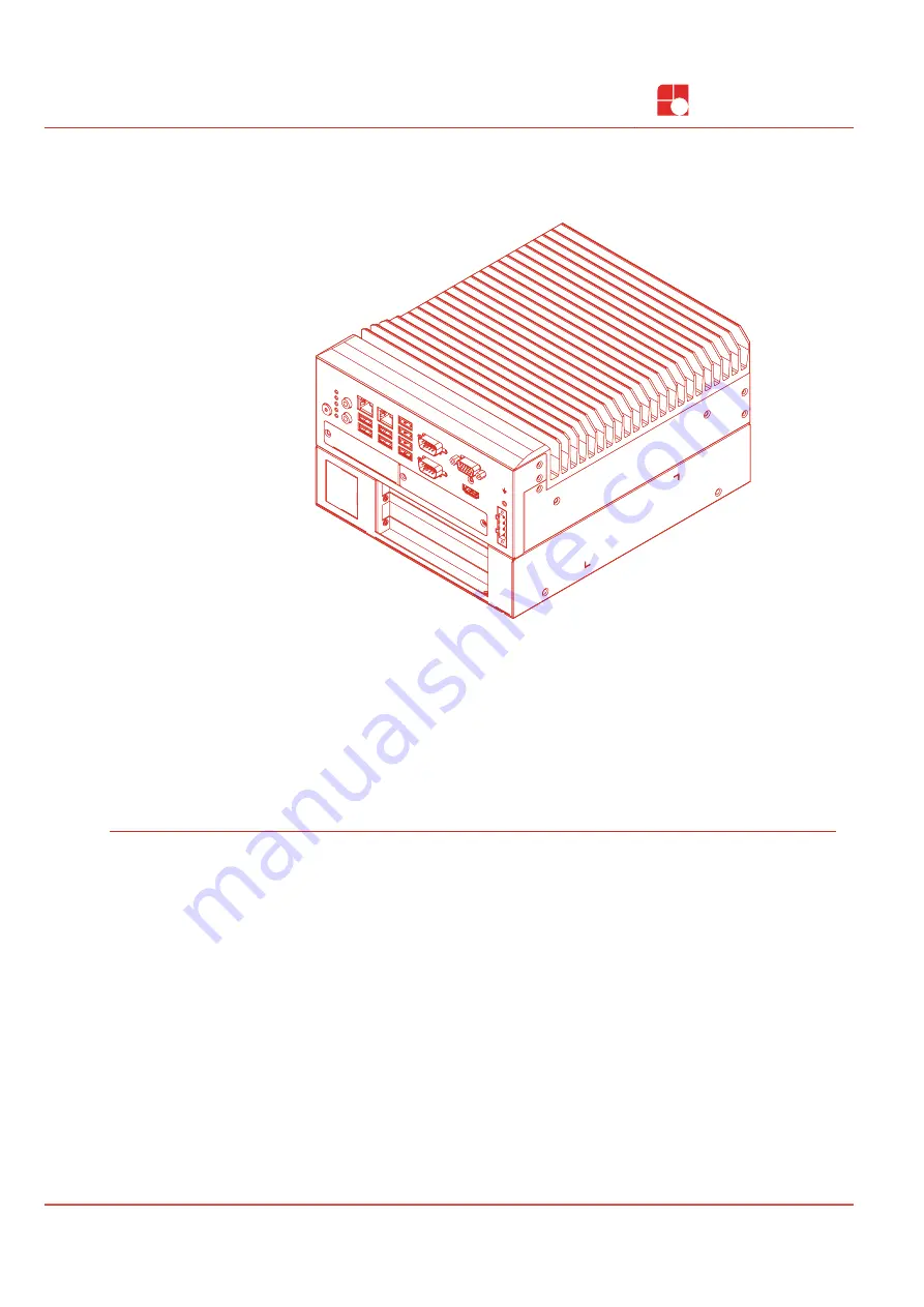
Instructions for Use
vicosys
®
6300
Multi-Camera System
999.995.428.10-en-2.1
© Vision & Control GmbH 2022
Страница 1: ...creating machine vision VISION CONTROL Instructions for Use vicosys 6300 Multi Camera System Instructions for Use vicosys 6300 Multi Camera System 999 995 428 10 en 2 1 Vision Control GmbH 2022 ...
Страница 2: ...is document on to third parties reproduce and communicate its contents in as far as this has not been expressly authorized Offenders will be liable for damages All rights are reserved with respect to patent utility sample and design patent registrations as well as for rights of use within the scope of copyright vicotar vicolux pictor vicosys and vcwin are registered trademarks of Vision Control Gm...
Страница 3: ...connecting Gig E vision cameras incl assembly 4 21 178 I O process interface Designation Description Order no Digital I O card ADDI DATA 16 in 16 outputs Open Emitter PNP Model APCIe 1500 4 21 170 Digital I O card ADLINK 16 in 16 outputs Open Collector NPN Model LPCIe 7230 4 21 171 Fieldbus interface Designation Description Order no PROFINET card HILSCHER Integration of a PROFINET interface Model ...
Страница 4: ...aces 18 5 5 Expansion Cards 19 5 5 1 Camera interface 4 port Gigabit Ethernet 19 5 5 2 Digital I O card ADDI DATA 20 5 5 2 1 Digital input channels 20 5 5 2 2 Digital output channels 21 5 5 3 Digital I O card ADLINK 22 5 5 3 1 Digital input channels 22 5 5 3 2 Digital output channels 24 5 5 4 PROFINET card HILSCHER 25 6 Commissioning 26 6 1 Unpacking 26 6 2 Mounting 26 6 3 Connecting 28 6 3 1 Conn...
Страница 5: ...terfaces 18 Image 9 Basic device USB interfaces 19 Image 10 Expansion Camera interface 4 x GigE 19 Image 11 Expansion Digital I O card ADDI DATA 20 Image 12 Schematic layout of digital input channels 1 to 16 20 Image 13 Schematic layout of digital output channels 1 to 16 21 Image 14 Expansion Digital I O card ADLINK 22 Image 15 Schematic layout of digital input channels 1 to 8 22 Image 16 Schemati...
Страница 6: ...cations in this instructions of use by authorised operative personnel who are aware of the safety rules and hazards If the device is planned to be used for any other purpose or in a different environment the express authorisation of the manufacturer must be obtained in advance Any modifications or adaptations required may only be made by the manufacturer 1 3 Improper Use All unintended use and all...
Страница 7: ...installations and working materials 1 5 Warranty and Liability The contents of this document have been checked carefully and correspond to current legislation and best practise at the time of going to press However the manufacturer shall not be liable for any damage arising from the use of this edition of the manual and rejects any warranty derived therefrom Within the bounds of the legal requirem...
Страница 8: ...situation with low risk resulting in minor or medium injuries if not avoided NOTICE Indicates a situation that may result in property damage 2 2 Safe Handling of the Device Read the following applicable safety instructions carefully and completely Follow the instructions for your own safety the safety of other people and to avoid damage to the device and the connected technical equipment Hazards g...
Страница 9: ...a 35 mm DIN rail TS35 4 40 218 Cameras Designation Description GigE Vision cameras Cameras with different resolutions and specifications monochrome colour NIR according to the requirements Accessories for the option Digital I O card ADDI DATA Designation Description Order no Terminal Board PX901 DG D Sub terminal board with LEDs for DIN rail mounting with screw terminal strips for connecting senso...
Страница 10: ...d DIN 50S 01 Terminal board with a 50 pin SCSI II connector for DIN rail mounting for connecting sensors actuators or similar to the I O expansion card of the device 4 40 288 I O cable ACL 10250 1 Cable for connecting the I O card LPCIe 7230 with the terminal board DIN 50S 1 length 2 m 4 40 289 10 999 995 428 10 en 2 1 Vision Control GmbH 2022 ...
Страница 11: ...s 7 Type plate 4 Ventilation opening front 8 MAC address optional 4 2 Interfaces and Connectors TX1 RX1 TX2 RX2 2 1 5 6 8 7 1 4 2 1 1 6 5 8 7 4 3 2 Image 2 Basic device interfaces and connectors 1 2 x Gigabit Ethernet 5 1 x Housing ground 2 8 x USB 6 Operating voltage input 3 2 x RS232 7 Process interface optional 4 1 x VGA 1 x HDMI 8 Camera interface optional Vision Control GmbH 2022 999 995 428 ...
Страница 12: ...data is being transferred TX2 RX2 COM2 LED for monitoring the data transmission status Green flashes when data is being transferred Green flashes when data is being transferred 1 Hard disk Displays the status of the hard disk Orange Data access Off no access 2 PWR Displays the status of the device Off no operating voltage Green operating voltage applied device is running Red operating voltage appl...
Страница 13: ...3 4 5 1 2 Image 4 Type plate 1 Serial number as 2D Data Matrix code 2 Serial number as plain text 3 Manufacturer information 4 Device designation 5 Version number MAC address For the PROFINET card HILSCHER configuration there is a label with the MAC address of the Profinet card next to the type plate Vision Control GmbH 2022 999 995 428 10 en 2 1 13 ...
Страница 14: ...vicosys 6300 Device Description 4 5 Technical Drawings Basic Device vicosys 6300 230 123 123 192 Image 5 Technical drawing vicosys 6300 14 999 995 428 10 en 2 1 Vision Control GmbH 2022 ...
Страница 15: ... 18 14 6 5 13 14 11 146 20 150 left slotted hole dimensions like 5 2 5 18 14 6 5 13 14 11 150 146 11 9 13 5 5 2 left slotted hole dimensions like Image 6 Technical drawing vicosys 6300 mounting plates Vision Control GmbH 2022 999 995 428 10 en 2 1 15 ...
Страница 16: ...ction 6 x USB 3 1 and 2 x USB 3 0 Communication interfaces 2 x RS232 process communication data transfer Camera interface 1 LAN 2 1 x GigE Vision no PoE Expansion card Camera interface 4 x GigE Vision with PoE Digital I O card ADDI DATA 16 IN 16 OUT PNP Expansion card process interface Digital I O card ADLINK 16 IN 16 OUT NPN Expansion card field bus PROFINET card HILSCHER Model CIFX 50E RE Video ...
Страница 17: ... TX2 RX2 2 1 5 6 8 7 1 4 2 1 1 2 Image 7 Basic device Ethernet interfaces 1 LAN 1 2 LAN 2 Characteristics LAN 10 100 1000 Mbps Ethernet interface 1 LAN 1 Integration of the device in a LAN suitable for process communication as well as parametrisation with the operating software vcwin Ethernet interface 2 LAN 2 Connection of a GigE vision camera The interface is not PoE capable The camera must be s...
Страница 18: ... Parameter Parameter Min Nom Max Baud rate 9 6 kBit s 1 115 2 kBit s Number of bits 8 Number of stop bits 1 Parity None Flow control None Galvanic decoupling Non existent 1 Factory setting 5 4 3 USB interfaces NOTICE Overheating due overload Each USB port can deliver a maximum output current of 900 mA Ports 1 2 3 4 5 6 and 7 8 are each secured with 1800 mA ADVICE Data loss due to incorrect disconn...
Страница 19: ...Gigabit Ethernet In the Camera interface 4 x GigE configuration the device has four GigE vision interfaces 1 2 3 4 PoE 1 Image 10 Expansion Camera interface 4 x GigE 1 4 x GigE Vision interfaces Characteristics LAN 10 100 1000 Mbps Connection 4 port 4 x RJ45 Power supply via PoE yes Status indicators LED Colour Status Description Off Power over Ethernet off PoE Red On Power over Ethernet on Off Po...
Страница 20: ...GND IO IN X INx GND GND Image 12 Schematic layout of digital input channels 1 to 16 Characteristics Polarity protection Galvanic decoupled Inputs have ESD protection and interference signal filter The input channels have a common GND connection GND IN Parameter Parameter Min Nom Max Number of inputs 16 Input voltage VIN DC 0 V 24 V 30 V 1 Input voltage Low 0 V 14 V Input voltage High 19 V 30 V Inp...
Страница 21: ...channels are supplied by the operating voltage VDD ESD protection and output signal filter The output channels have a common GND connection GND OUT Parameter Parameter Min Nom Max Number of outputs 16 Operating voltage VDD DC 11 V 1 24 V 36 V Output current per output 500 mA Output current for 8 outputs 1 5 A Short circuit current output 2 1 5 A Turn on time 3 50 µs Turn on time 3 75 µs Galvanic d...
Страница 22: ...Collector Connector 50 pin SCSI II Connector 5 5 3 1 Digital input channels Digital input channels 1 to 8 IN X L IN X H 1 2 kΩ 0 5 W INx GND Image 15 Schematic layout of digital input channels 1 to 8 Characteristics Non polarised Galvanic decoupled among each other For each input channel both input signals are lead out to the connector Digital input channels 9 to 16 COM IN IN X 1 2 kΩ 0 5 W INx GN...
Страница 23: ...eter Parameter Min Nom Max Number of inputs 16 Input voltage VIN DC 0 V 24 V 24 5 V 1 Input voltage Low 0 V 1 5 V Input voltage High 5 V 24 V Input current Low 0 mA 1 5 mA Input current High 4 2 mA 20 mA Input resistance 1 2 kΩ 0 5 W Switching frequency 0 Hz 10 kHz Galvanic decoupling present 1 Higher input voltages destroy the respective input channel Vision Control GmbH 2022 999 995 428 10 en 2 ...
Страница 24: ...put channels have a common GND connection GND OUT Parameter Parameter Min Nom Max Number of outputs 16 Operating voltage VDD DC 5 V 24 V 35 V Output current per output 1 500 mA Output current of all outputs 2 370 mA Output current of all outputs 3 130 mA Galvanic decoupling present 1 Duty cycle unlimited On single output channel 2 Duty cycle max 25 ms ON all 16 output channels simultaneously duty ...
Страница 25: ... for firmware Yellow On Bootloader netX romloader is waiting for second stage bootloader SYS Off Power supply for the device is missing or hardware defect Off No error Flashing DCP signal service is initiated via the bus SF System Failure Red On Watchdog timeout channel generic or extended diagnosis present system error Off No error Flashing No data exchange BF Bus Failure Red On No configuration ...
Страница 26: ...gised state NOTICE Damage or destruction caused by overheating Do not cover the device Do not operate the device packed Leave sufficient room for air circulation Do not cover the fan Operate the device in ambient conditions according to the specifications in these instructions of use Wall and table mounting The device is designed for wall and table mounting Note the installation positions The scop...
Страница 27: ...vicosys 6300 Commissioning Mounting right side Mounting rear side Mounting bottom side Vision Control GmbH 2022 999 995 428 10 en 2 1 27 ...
Страница 28: ...thernet interfaces Connect the device with the LAN via Ethernet cable Use the Ethernet interface LAN 1 for process communication and parametrisation Use the Ethernet interface LAN 2 for direct connection to a PC 6 3 2 Connect the RS232 interface For serial communication connect the device to the process environment using an RS232 cable 6 3 3 Connect a monitor A monitor can be connected to the devi...
Страница 29: ...E an external power supply is required Connect these according to manufacturer s specifications Connect the cameras to the corresponding ports Use of switches By using a Gigabit Ethernet switch up to 8 cameras can be connected to the device However in this process the bandwidth is divided between the cameras used so the full frame rat may not be possible ADVICE Requirements of the switch Support f...
Страница 30: ...ng two variants I O cable with 2 x D Sub sockets and terminal board I O cable with 1 x D Sub socket and open cable end Pin assignment Digital Input 1 Digital Input 7 Digital Input 9 Digital Input 5 Digital Input 3 Digital Input 11 Digital Input 13 Digital Input 15 24 V external outputs 0 V external inputs Digital Output 1 Digital Output 3 Digital Output 5 Digital Output 7 Digital Output 9 Digital ...
Страница 31: ...channel 11 17 Green red OUT 13 Digital output channel 13 18 Green black OUT 15 Digital output channel 15 19 Grey blue Do not use 20 Brown IN 2 Digital input channel 2 21 Yellow IN 4 Digital input channel 4 22 Pink IN 6 Digital input channel 6 23 Red IN 8 Digital input channel 8 24 Violet IN 10 Digital input channel 10 25 Blue red IN 12 Digital input channel 12 26 Brown green IN 14 Digital input ch...
Страница 32: ... board 3 Connect the ground potential GND of the digital inputs and outputs of the device with the ground potential GND of the control voltage of the device to be controlled 4 Connect the digital I Os of the unit to be controlled to the DIN 50S 01 connection board Pin assignment VDD EICOM IDO_7 EICOM EICOM IDO_6 IDO_5 IDO_4 IDO_3 IDO_2 IDO_1 IDO_0 IDI_3H IDI_3L IDI_2H IDI_2L IDI_1H IDI_1L IDI_0H I...
Страница 33: ...el 11 23 IDI_9 Digital input channel 10 24 IDI_8 Digital input channel 9 25 EOGND GND supply voltage digital outputs 26 VDD 24 VDC supply voltage digital outputs 27 ISO5V Galvanic decoupled 5V output 28 EICOM Common ground or signal input channels 9 to 16 29 EICOM Common ground or signal input channels 9 to 16 30 IDO_14 Digital output channel 15 31 IDO_15 Digital output channel 16 32 IDO_12 Digita...
Страница 34: ...g ground 2 4 pin operating voltage connector 1 Ensure that the supply voltage is switched off 2 Connect the positive voltage plus to V DC and the negative voltage ground to GND 3 Connect the housing ground 4 Plug the operating voltage connector to the device and tighten the screws Pin Signal Description 1 GND Ground 2 V DC Supply voltage 3 V DC Supply voltage 2 1 4 3 4 GND Ground Gerät einschalten...
Страница 35: ... having started vcwin you should choose the port to which the vision system is connected by calling Communication Interface from the menu Connecting the device with vcwin Connect the device by calling Communication Connect 6 4 1 Create a LAN connection direct connection 1 Start the operating software vcwin on the PC 2 Open the window Communication Parameters by calling Communication Interface The ...
Страница 36: ...et For devices in different subnets the configuration data must be entered manually 6 4 2 Create a serial connection The Serial interface on the device is used for serial communication 1 Connect the device directly to the PC using a RS232 cable 2 Start the operating software vcwin on the PC Configure the interface by calling Communication Interface in the menu 1 2 4 5 3 3 Switch to the RS232 tab 4...
Страница 37: ...tage If the supply voltage is not to be switched off the unit can be switched off by pressing the PWR key 7 2 Operation via Software ADVICE Creating and managing programs are performed using the operating software vcwin The vcwin Instructions for Use is included on the USB stick scope of delivery Further information on the use of the software can be found on the homepage http www vision control co...
Страница 38: ...irectly to the housing and the housing must not be bathed The interfaces must be clean and dry before the device is connected and put into operation 8 2 Service Technical Support Please contact our technical support if you have any technical questions concerning our products We will be glad to be of service Monday to Thursday 8 00 to 17 00 and Friday 8 00 to 15 00 Vision Control GmbH Mittelbergstr...
Страница 39: ...must also always be in a way that does not harm the environment which means it must be done in accordance with the currently valid legal regulations Please contact the manufacturer your local specialist dealer or the relevant national authority for the proper disposal of old devices The electrical and electronic components must be sent to a specialist recycling company or to the manufacturer for p...
Страница 40: ...Vision Control GmbH Mittelbergstraße 16 98527 Suhl Germany Telephone 49 0 3681 7974 0 Telefax 49 0 3681 7974 33 www vision control com ...