background image

11 

1. Move the machine to the appointed disposal area. 
2. Turn off the main switch (47). 
3. Take off the recovery tank (2), clean and rinse both solution/recovery tank, and drain out. 
4. Take off all vacuum kits, gasket, filter, clean and re-install. 
5. Check the recovery tank lids gasket ring and the vacuum rubber connector (18) between two tanks 
are integrity or not.. 


NOTE 

The gasket ring of recovery tank and the rubber connector between two tanks create 
vacuum in the tank. If necessary, replace them


MACHINE STRUCTURE 

1. Recovery tank lid 
2. Recovery tank 
3. Solution tank 
4. Brush cover 
5. Protective rollers 
6. Brush 
7. Front handle shell 
8. Control panel 
9. Rear handle shell 
10. Handle rubber 
11. Handle iron pipe 
12. Squeegee vacuum assembly 
13. Squeegee suction assembly 
14. Left positioning 
15. Right positioning 
16. Batteries 
17. Latch 
18. Rubber sealing 
19. Limit hose joint 
20. Inlet 
21. Solution filter 
22. Solution tank drain 
23. Wheels on fixed axle 
24. Handle left and right 
25. Handle rotate lever 
26. Squeegee lift lever 
27. Squeegee string 
28. Box circuit 
29. Charger 
30. Battery charge indicator 
31. Solution flow control lever 
32. Electromagnetic valve data 
33. Squeegee 

USER MANUAL 

Содержание AS380/15B-AU

Страница 1: ...VF89865 REV 01 2015 7 13 AS380 15B AU User Manual Original instructions Company information www vipercleaning eu info eu vipercleaning com...

Страница 2: ......

Страница 3: ...WKH PDFKLQH FRQIRUPLW ZLWK WKH ODZ LQ IRUFH NOTE Two copies of the original declaration of conformity are provided together with the machine documentation IDENTIFICATION DATA The machine serial numbe...

Страница 4: ...ubber dryer Instructions for use Manual Electronic battery charger manual if installed Scrubber dryer Spare Parts List SAFETY The following symbols indicate potentially dangerous situations Always rea...

Страница 5: ...battery charging produces highly explosive hydrogen gas During battery charging lift the recovery tank and perform this procedure in well ventilated areas and away from naked DPHV WARNING Carefully r...

Страница 6: ...95 KHQ XVLQJ RRU FOHDQLQJ GHWHUJHQWV IROORZ WKH LQVWUXFWLRQV RQ WKH ODEHOV RI WKH GHWHUJHQW ERWWOHV 7R KDQGOH RRU FOHDQLQJ GHWHUJHQWV ZHDU VXLWDEOH JORYHV DQG SURWHFWLRQV Do not use the machine as a m...

Страница 7: ...tank 2 as shown in the relevant paragraph 3 Unscrew the bolt from batteries 16 then remove or change 4 Install the batteries on the machine according to the diagram below 5 Install the recovery tank...

Страница 8: ...rotate the brush pad clockwise until it is released from drive wheel hub WARNING Do not turn on the machine in this position as below The brush pad could disengage and cause injury Squeegee installati...

Страница 9: ...ain 2 Rinse the solution tank with clean water after every use This will help prevent chemical build up and clogging of the solution lines 3 Screw up the drain cap 22 Recovery tank draining NOTE Recov...

Страница 10: ...Remove the brush pad holder 2 Empty the tanks as shown in the previous parsagraph 3 Perform the daily maintenance procedures see the maintenance chapter 4 Store the machine in a clean and dry place wi...

Страница 11: ...or carbon brush check or replacement 2 Vacuum system motor carbon brush check or replacement 2 1 And after the first 8 working hours 2 This maintenance procedure must be performed by an authorized vip...

Страница 12: ...harp debris SQUEEGEE BLADE CHECK AND REPLACEMENT 1 Take off the squeegee as shown in the previous paragraph 2 Check to see if the edge of the front rear blades are cracked or split if necessary replac...

Страница 13: ...ce them MACHINE STRUCTURE 1 Recovery tank lid 2 Recovery tank 3 Solution tank 4 Brush cover 5 Protective rollers 6 Brush 7 Front handle shell 8 Control panel 9 Rear handle shell 10 Handle rubber 11 Ha...

Страница 14: ...hose 35 Squeegee wheels 36 Axle 37 Thumb nut 38 Vacuum system motor 39 Brush motor 40 Drive belt 41 Belt 42 Squeegee rotation plate 43 Squeegee lift plate 44 Squeegee fixing plate 45 Motor fixing pla...

Страница 15: ...13 USER MANUAL...

Страница 16: ...ion tank capacity 15L Recovery tank capacity 15L Wheel diameter 254MM Brush motor data 24V 250W Vacuum motor data 24V 300W Electromagnetic valve data 24V Maximum gradient 2 Sound lever 68 dBA Batterie...

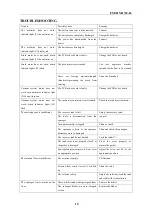
Страница 17: ...r key board Vacuum system motor does not work brush indicator lights 53 flash The vacuum system motor is overloaded Check the vacuum system motor The suction power is insufficient The recovery tank is...

Страница 18: ...Ltd Unit 1 13 Bessemer Street Blacktown NSW 2148 Phone 1300 556 710 E mail Warranty au nilfisk com NEW ZEALAND Nilfisk Limited Suite F Building E 42 Tawa Drive Albany Auckland 0632 Phone 64 9414 1996...

Страница 19: ...Company information www vipercleaning eu info eu vipercleaning com...

Отзывы: