background image

6

Section 3:  Product Overview

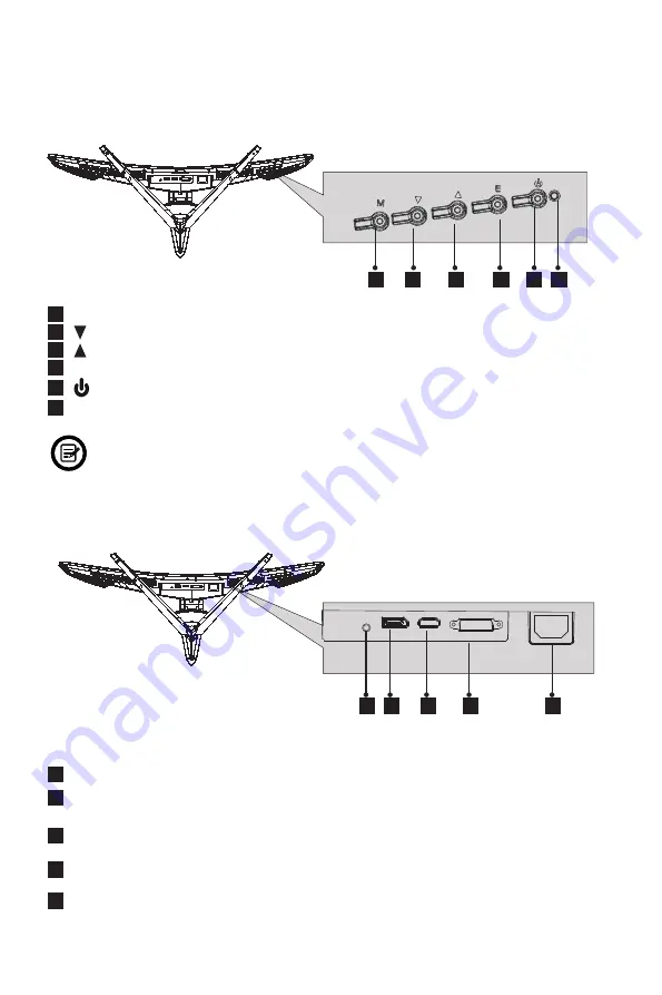
3.1 – Monitor Buttons

 7


Audio Output

:

 Insert the audio cable for output of audio signals.

 8


DP Connector

: Insert one end of the DP cable into the computer’s DP output and con-

nect the other end to the monitor’s DP port.

 9


HDMI Connector

: Insert one end of the HDMI cable into the computer’s HDMI output 

and connect the other end to the monitor’s HDMI port.

10


DVI Connector

:Insert one end of the DVI cable into the computer’s DVI output and 

connect the other end to the monitor’s DVI port.

11

  Power Connector

: Insert the Power Cable to supply power to the monitor.

 1

   M Menu Button

: Press to display the OSD menu or enter sub-menus.

 2


Down Button

: Press to move down in the menus.

 3


Up Button

: Press to move up in the menus.

 4


E Exit Button

:


Press to exit.

 5


Power Button

: Press to turn the monitor on/off.

 6


LED Indicator

Changes colors to indicate status. Refer to Section 8.


  The E button can also be used to switch between two color gamuts when a compatible 

graphics card and either HDMI or DP connections are in use.

3.2 – Monitor Ports

 2

 3

 4

 5  6

 1

 7  8

 9

10

11

Содержание GN35LD

Страница 1: ...D In order to continue serving our customers and providing the best products our product information including our user manuals may receive updates from time to time Please check our website for the l...

Страница 2: ......

Страница 3: ...6 3 DP Connectivity 11 6 4 HDMI Connectivity 11 6 5 DVI Connectivity 11 Section 7 Basic Operation 12 Section 8 Indicator Light 12 Section 9 OSD Setup 13 9 1 OSD Menu Functions 14 Section 10 LED Effect...

Страница 4: ...nitor 5 Do not spray cleaner and or any kind of liquid directly onto the monitor s screen or any part of the monitor 6 Do not insert anything into any part of the monitor especially the ventilation op...

Страница 5: ...Attached Bracket Stand Base x 1 Cover Base x 1 Cover x 1 Power Cable x 1 AC 100 240V 50 60Hz NO 2 Screws x 3 NO 3 Screws x 4 for Wall Mounting NO 1 Screw x 1 DP Cable x 1 Screwdriver x 1 Allen Key x 1...

Страница 6: ...he computer s DVI output and connect the other end to the monitor s DVI port 11 Power Connector Insert the Power Cable to supply power to the monitor 1 M Menu Button Press to display the OSD menu or e...

Страница 7: ...am Stand Stem 2 Take out the two parts of the stand and use the included allen key and a NO 1 screw to attach them Use only the NO 1 screw provided Stand Base Stand Stem NO 1 screw 1x Bracket 3 Take o...

Страница 8: ...uld click into place 6 Place the monitor on your desktop or table after completing the installation and carefully pull or push it up or down to adjust the height Stand Stem 7 Press the button to remov...

Страница 9: ...oam Stand Stem 2 Remove the original screws x 4 1 from the opening in the back of the monitor and install the UP DOWN converters with the NO 3 screws provided Do not discard the original screws They a...

Страница 10: ...to the power connector and then plug the other end into an AC outlet Power Cable 6 2 Connecting Your Earphones When earphones are plugged in no sound will be emitted from the speakers Earphones Not i...

Страница 11: ...e Included 6 4 HDMI Connectivity In order for the Monitor to receive HDMI signals from the computer use the HDMI cable to connect the Monitor to the computer HDMI OUTPUT PC HDMI Cable Not included 6 5...

Страница 12: ...u cannot locate the power button please refer to the Product Overview Section on page 5 AMD FreeSync If desired you can use the monitor s AMD FreeSync feature The feature itself is on by default In or...

Страница 13: ...enter the OSD screen Figure 2 DP Resolution 2560x1440 60Hz Input Source Brightness Contrast Color Setting Picture Quality Setting Display Multi Window Audio Other DVI HDMI DP Window 1 InputSource DP...

Страница 14: ...Low Blue Light 0 100 Set the display blue light ltering function Hue Saturation Hue Saturation Set the hue and saturation of the display Picture Quality Setting Bypass On Off Turn the bypass function...

Страница 15: ...Top Right Top Left Bottom Right Bottom Left Adjust the PIP PBP window position Swap NONE Swap the two channel signal source of only the PIP PBP 2 screens function Other Language English Espa ol Set OS...

Страница 16: ...t the desired option and press M to confirm the setting 4 Press E to exit the current settings Items Options Description Color Colorful White Purple Blue Cyan Green Yellow Red Select the the desired c...

Страница 17: ...sure that its settings are in mirror mode and the device itself is powered on The image is out of focus Ensure the video cable is inserted properly at both ends The screen is ashing Try an alternativ...

Страница 18: ...s card is compatible with the monitor Inspect if the pins in the interface are curved Dim image Adjust the brightness and contrast ratio Image jitter moire pattern Nearby electric equipment may interf...

Страница 19: ...ature is supported while X means it is not supported 12 2 PBP Picture by Picture Resolution Information While using this feature and in order to obtain an optimal viewing experience it is recommended...

Страница 20: ...90 non condensation Height Adjustment Yes VESA Mounting Need VESA additional bracket Dimension With Stand 32 97 x 15 94 x 20 66 in Weight Net Gross Weight 20 57 lbs 29 56 lbs 13 1 Resolution Compatibi...

Страница 21: ...855 229 9472 for service request When a product or part is exchanged any replacement item becomes your property and the replaced item becomes WP s property This warranty only covers technical hardware...

Страница 22: ...with the instructions may cause harmful interference to radio communications However there is no guarantee that interference will not occur in a particular installation If this equipment does cause ha...

Страница 23: ......

Страница 24: ...COPYRIGHT 2017 VIOTEK ALL RIGHTS RESERVED...

Отзывы: