3
EN
The instruction manual is downloadable from the site
www.vimar.com
EN
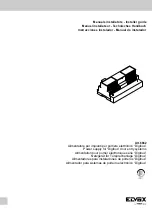
TECHNICAL CHARACTERISTICS OF POWER SUPPLIER ART. 6942
Additional power supply for intallation with more than 50 digital distributors
(type 949B) or 280 internal code type interphones (monitors).
Used only for line supplying the interphones (monitors) or for switchboard
supply ; housed in a grey thermoplastic case.
Designed for mounting on equipment panels with DIN omega rails (12 mo-
dles), or wall fixing with masonry plugs.
Main power supplier data:
- Dimensions: 208x135x72
- Power supplier weight:: 1,5Kg
- Power supply: 230V A.C. (+6/-10%) 50-60Hz (other power supplies are
available on request)
- Maximum absorbed power: 70VA
- Low voltage supply: 13,5VDC 1,5A continuous cycle (maximum of 50
distributors Art. 949B and one entrance panel, or 200 appliances
type Art. 6204, 887B or 887B/1 and one entrance panel).
- Lock output: 15V rectified 1A intermittent cycle (30 sec. ON, 480 sec.
OFF)
- Outputs for activation of additional functions: 12VDC 0,15A intermittent
cycle 255 sec. ON, 255 sec. OFF (maximum of 1 relay type 170/001,
etc.).
Built-in protection features:
- Transformer primary: PTC tipo SIEMENS C840
- 1st secondary, driving internal electronic circuits: Fusibile F 3,15AL 250V
(F1)
- Secondary transformer winding supplying door lock and/or lamps: Fusi-
bile F 3,15AL 250V (F1)
- Generator of electronic call
- Electronic interphone riser or panel short-circuit or overload cutout
LED status indicator unit:
L1 - Lock power supply (15 and S1 terminals)
YELLOW LED
L2 - Door lock command (terminal S)
YELLOW LED
L3 - Auxiliary function 1 (terminal F1)
GREEN LED
L4 - Auxiliary function 2 (terminal F2)
YELLOW LED
L6 - Digital circuit power supply (terminals 4 and 5)
RED LED
Description of power supplier terminal functions:
CH Not used
S
Door lock release control line.
This terminal is used by the entrance panels or switchboard to rele-
ase the door lock for the corresponding entrance panel or switchbo-
ard. When terminal S is shorted to terminal 4, terminal S1 is shorted
to terminal 0 (15V rectified) and LEDS L1 and L2 illuminates. Termi-
nal S1 remains shorted for the time terminal S is activated.
F1
Auxiliary function 1 activation control line.
This terminal is used by the entrance panels or switchboard to acti-
vate function F1. When terminal F1 is shorted to terminal 4, the vol-
tage at terminal R1 increases to 12 Vdc and remains at this voltage
for the time terminal F1 is shorted. Activation of the function is signal-
led by illumination of LED L3.
F2
Auxiliary function 2 activation control line.
This terminal is used by the entrance panels or switchboard to acti-
vate function F2. When terminal F2 is shorted to terminal 4, the vol-
tage at terminal R2 increases to 12 Vdc and remains at this voltage
for the time terminal F2 is shorted. Activation of the function is signal-
led by illumination of LED L4.
3
Not used
4
Digital circuit power line (negative).
5
Digital circuit power line (+ 13.5 Vdc 1.5A).
Energisation of terminal 5 is indicated by illumination of LED L6.
4
Auxiliary function power line (negative).
R1
Auxiliary function 1 power line (+ 12 Vdc 0.15 A).
This terminal activates a relay when function F1 is activated. When
terminal F1 is activated, terminal R1 is powered by a 12 Vdc vol-
tage.
4
Auxiliary function power line (negative).
R2
Auxiliary function 2 power line (+ 12 Vdc 0.15 A).
This terminal activates a relay when function F2 is activated. When
terminal F2 is activated, terminal R2 is powered by a 12 Vdc vol-
tage.
S1
Door lock release line (1A).
When terminal S is activated, terminal S1 is shorted to terminal 0 and
LEDS L1 and L2 illuminates. The line is protected by a fuse F 3,15A
250V (F2)
15-0 15V (rectified) line: 1A door lock release.
These terminals power the name card illumination lamps, door lock
and services.
The line is protected by a fuse F 3,15A 250V (F2)
PRIM Power terminals: 230 Vac +6/-10% 50-60Hz.
These terminals are mounted under the thermoplastic protection
marked by the symbol and are used to power the relay con-
nections. No earth terminal is fitted, this being a power supplier con-
structed to Class 2 specifications.
INSTALLATION
The 6942 power unit must be located in a dry, dustfree place away from
heat sources. The location should afford ease of access for the purposes
of inspection and setting operations. The unit can be mounted either to the
wall, using the fixing plugs provided, or to an equipment panel with DIN
omega rails. Before any connections are made, checks should be made
(using a normal tester) to ensure that there are no conductors broken or
short circuiting. It is good practice to run system wiring and mains wiring
through separate conduits. To ensure maximum user safety, all devices
operate at low voltage and are separated from the mains by an isolation
transformer of high specification. It is recommended in any event that a cir-
cuit breaker of adequate rated capacity should be wired between the mains
supply and the equipment. Thereafter :
1) Wire up the connection terminals as eclosed diagrams of Art. 6941 and
6948 power supplies.
2) Wire up the power supply terminals located under the rear shield.
3) Switch on the unit : following initial acclimatization of the system, LED
L6 should remain alight, indicating that power lines to the entrance
panel/doorlock and the user interphones are on
INFORMATION FOR USERS UNDER DIRECTIVE 2002/96
(WEEE)
In order to avoid damage to the environment and human health as
well as any administrative sanctions, any appliance marked with
this symbol must be disposed of separately from municipal waste, that is it
must be reconsigned to the dealer upon purchase of a new one. Applianc-
es marked with the crossed out wheelie bin symbol must be collected in
accordance with the instructions issued by the local authorities responsible
for waste disposal.
Product is according to CE mark and directives:
- EC Directives 2004/108/EC and following norms.
- EC Directives 2006/95/EC (73/23/CEE) and following norms.
Power supplies constitute SELV sources in compliance with the require-
ments stipulated in Article 411.1.2.2 of CEI standard 64-8 (ed. 2003).
INSTALLATION RULES.
Installation should be carried out observing current installation regulations
for electrical systems in the Country where the products are installed.
Ensure clearance around the appliance so there is sufficient ventilation.
There must be no dripping or splashes of water on the appliance.
WARNING
: To prevent injury, the appliance must be secured to the wall as
described in the installation instructions.
Above the power supply there must be a bipolar circuit breaker that is eas-
ily accessible with a contact gap of at least 3 mm.
CONFORMITY.
LV directive
EMC directive
Standards EN 60065, EN 61000-6-1, EN 61000-6-3.

