


6
ELEKTRISK INSTALLASJON
Elektrisk installasjon skal utføres av
autorisert installatør og i samsvar med
gjeldene forskrifter for elektriske anlegg.
Villavent avtrekksvifte er ferdig internt koblet.
Elektriker skal kun sørge for strømtilførsel
(10A/230V + jord) til kjøkkenhetten, og
deretter forbinde kjøkkenhetten med
avtrekksviften.
Hurtigkobling:
Både avtrekksviften og kjøkkenhetten er
utstyrt med kabel og en ferdigkoblet, spesiell
skjøtekontakt. Kjøkkenhetten har, i tillegg til
skjøtekontakt, ledning med støpsel som skal
kobles til 10A/230V jordet stikkontakt.
For elektrisk installasjon med skjøtekontakt
henvises til egen anvisning som følger
vedlagt.
Fast opplegg u/skjøtekabel:
Skjøtekontakt med kabel kobles fra
tilkoblingsklemme, både i kjøkkenhettens og
avtrekksviftens koblingsboks, og fjernes.
Membranniplene med strekkavlaster i
avtrekksviften erstattes av standard
skapmuffer (Ø16 mm).
Veggboks plasseres på vegg bak krydderhylle
eller ventilatorskap, 1620 mm fra golv og 140
mm fra skapets venstre sidevange.
Kjøkkenhettens koblingsboks er plassert foran
på kjøkkenhettens topp. Lokket til
koblingsboksen tas av og strømtilførsel
(10A/230V + jord) føres via veggboks inn til
klemme nr. L og N, jord til klemme nr. 3 i
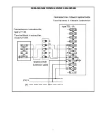
koblings-boksen. Deretter forbindes hettens
koblingsklemmer med klemmer i ventilasjons-
enhetens koblingsboks. Se koblings-
anvisninger neste side.
ELECTRICAL INSTALLATION
Electrical installation to be made by
authorized installer and in correspondance
with regulations in force.
The ventilation unit (Villavent extract fan or
heat recovery unit) is internally wired to
numbered terminals. The electrical connection
is therefore limited to connecting the
cookerhood to mains supply (10 A/230 V +
earth. For the UK marked, 13A/240V) and
connecting the hood to the ventilation unit.
Electrical quick connection:
The Villavent ventilation units and cookerhood
are both equipped with cable and special plug
for safe and quick electrical connection. In
addition, the cookerhood is equipped with
cable and plug for 10 A/230 V + earth
connection (For the UK marked, 13A/240V).
For electrical connection using special
extension cable, see separate instructions.
Traditional electrical connection:
Disconnect and remove cable and special
plug from terminal block in ventilation unit and
cookerhood. The cable glands to be replaced
by standard electrical cable entry (Ø16 mm).
When using a cookerhood there must be a
fused spur provision for the mains supply. The
spur box should be mounted on the wall, 1620
mm from the floor and 140 mm from the left
side of the cookerhood.
Electrical connection box is located on top of
the cookerhood. Remove the cover and lead
current supply (10 A/230 V + earth. For the
UK marked, 13A/240V) via spurbox to
terminal L and N, earth to terminal no 3.
Connect terminals in the cookerhood to
terminals in the ventilation unit. See wiring
diagrams next page.
Содержание TSL-1/A
Страница 7: ...7 KOBLINGSANVISNING WIRING DIAGRAM...


