

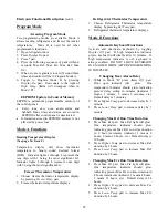


Speed Control Interface
1.
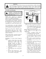
Position:
2. Circuit:
3. The microcomputer will wait for
a speed information in order to
start.
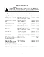
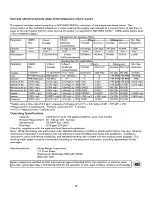
4. The speed signal wave form (continuous pulse train) shall be as follows:
5. The maximum and minimum rating for speed input signals are:
INPUT VOLTAGE SYMBOL Min Type Max Unit
HIGH
Vhigh
4.5
5.0
5.5
V
LOW
Vlow
-0.2
0
0.2
V
REVERSE
VOLTAGE
VR
6
V
ISOLATION
VOLTAGE
(AC
for
1
min.)
Viso
5
V
FORWARD
CURRENT
IF
3
5
10
mA
REVERSE
CURRENT
IR
10
µ
A
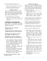
The pulse frequency (edge sensitive, duty cycle from 10 to 90% is OK) will determine the motor
speed as shown in the curve below:
6. Minimum speed 1600RPM -- Maximum speed 4500 RPM
7. If the inverter does not receive the speed signal for more than 33 shaft turns, the motor stops.
30
Содержание DFSB483D
Страница 1: ...VCSB483D DFSB483D DDSB483D COVER F90597...
Страница 4: ...VCSB483D with ICE and WATER 4...
Страница 5: ...CABINET AIR FLOW 5...
Страница 6: ...MACHINE COMPARTMENT AIR FLOW 6...
Страница 7: ...REFRIGERANT FLOW 7...
Страница 8: ...WATER FLOW 8...
Страница 27: ...VCSB483 WIRING DIAGRAM 27 27...
Страница 28: ...VCSB483D WIRING DIAGRAM DISPENSER MODEL 28...
Страница 38: ...CONTROL BOARD OPERATION 38...
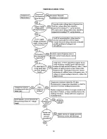
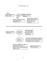
Страница 39: ...TROUBLESHOOTING 39...
Страница 40: ...TROUBLESHOOTING con t 40...
Страница 45: ...45...


