


EQUIPMENT AND TOOLS
A separate set of hoses and hand valves must be maintained for use with sealed systems
with R134a refrigerant. Equipment used with CFC refrigerants will contaminate R134a
(HFC) sealed systems.
EQUIPMENT DESCRIPTION
ILLUSTRATION
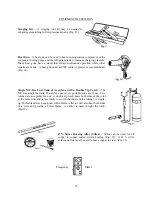
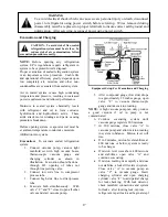
Tank of Liquid Refrigerant –
Care should be
taken to be sure the proper refrigerant is
available. (Fig. 1)
Handle the tank of liquid refrigerant
properly.
The contents of the tank are under
pressure. Observe the following precautions and
DO NOT
:
•
Drop or handle the tank roughly
•
Tamper with any installed safety relief valves
•
Store the tank in direct sunlight or in a damp
location.
•
Heat the tank above 125
°
F.
•
Refill the tank
Empty tanks should be disposed of properly.
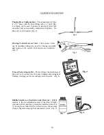
Charging Scale –
An electronic or
computerized charting scale measures the
amount of liquid refrigerant charge that is
ispensed into a sealed system. (Fig. 2)
f refrigerant necessary to back flush a
ystem.
onnected to the 45
°
threaded fitting. (Fig. 3)
d
The amount of refrigerant dispensed into the
sealed system is indicated on a Liquid Crystal
Display (LCD). The LCD is calibrated in .5
ounces or .01 gram increments or smaller. The
charging scale can be used to monitor the
amount o
s
Charging Hose Configuration
– One hose 4 to
6 feet long should be attached to a pigtail
consisting of a ball type hand valve with a 45
°
threaded fitting. A low-loss adapter should be
c
13
Содержание DFSB483D
Страница 1: ...VCSB483D DFSB483D DDSB483D COVER F90597...
Страница 4: ...VCSB483D with ICE and WATER 4...
Страница 5: ...CABINET AIR FLOW 5...
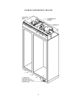
Страница 6: ...MACHINE COMPARTMENT AIR FLOW 6...
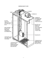
Страница 7: ...REFRIGERANT FLOW 7...
Страница 8: ...WATER FLOW 8...
Страница 27: ...VCSB483 WIRING DIAGRAM 27 27...
Страница 28: ...VCSB483D WIRING DIAGRAM DISPENSER MODEL 28...
Страница 38: ...CONTROL BOARD OPERATION 38...
Страница 39: ...TROUBLESHOOTING 39...
Страница 40: ...TROUBLESHOOTING con t 40...
Страница 45: ...45...


